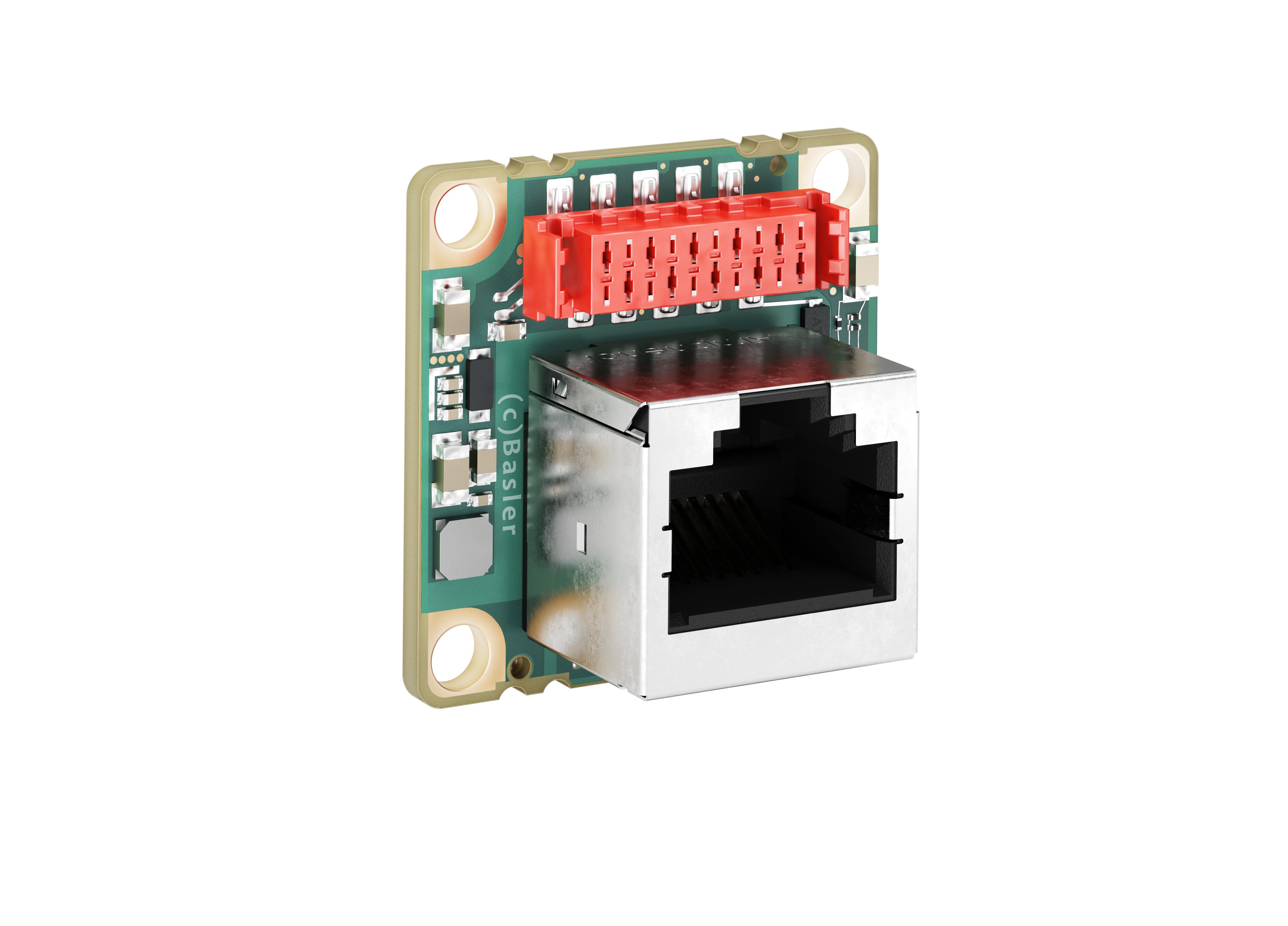
Interface Board dart M GigE RJ45 PoE#

规格#
通用规格#
| 规格 | dart M GigE RJ45 PoE |
|---|---|
| 订单号 | 109248 |
| I/O 线路 | 1 opto-coupled input line 1 general purpose I/O (GPIO) line 1 general purpose output (GPO) line |
| 大小 | 27.3 x 27.3 x 25.4 mm |
| 重量 | < 12 g |
| 符合标准 | CE (includes RoHS), EAC, KC, IEEE 802.3af (PoE) |
机械规格#
尺寸和安装点#
→ Download the CAD/technical drawing.
要求#
电气要求#
警告 — 触电和火灾危险/Risque de choc électrique et d'incendie
使用未经批准的电源可能会导致触电或火灾,从而可能造成严重伤害或死亡。
- 必须使用符合安全特低电压 (SELV) 和限功率电源 (LPS) 或电源 1 (ES1) 和电源 2 (PS2) 要求的电源。
- 如果您使用供电集线器和供电开关,它们必须满足上述要求。
Les blocs d'alimentation non approuvés peuvent causer des décharges électriques ou des départs de feu, ou les deux. Celles-ci représentent un risque de mort ou de blessure grave.
- Vous devez utiliser un bloc d'alimentation conforme aux exigences Safety Extra Low Voltage (SELV) et Limited Power Source (LPS) ou Electrical Source 1 (ES1) et Power Source 2 (PS2).
- Si vous utilisez un hub alimenté ou un switch alimenté, ils doivent être conformes aux exigences ci-dessus.
NOTICE – Incorrect voltage can damage the board.
相机供电和 I/O 供电必须符合下文指定的安全工作电压范围。
不要在 I/O 线路上使用负电压。
相机电源#
The GigE RJ45 PoE interface board supports Power over Ethernet (PoE). Power must comply with the IEEE 802.3af specification.
The voltage converter has an efficiency of at least 75 % at 2 W and above. To calculate the power requirement of the whole camera, divide the power requirement of the camera module by the efficiency of the interface board, i.e.
公式
Camera power requirement = Power requirement of camera module / Interface board efficiency
Example: 2 W / 75 % = 2.7 W
Output Power#
The GigE RJ45 PoE interface board is designed for a maximum output power of 6 W. This power must not be exceeded.
光电耦合 I/O 输入线路#
| 电压 | 描述 |
|---|---|
| 30 VDC | Absolute maximum. This voltage must never be exceeded. Doing so may damage the board and voids the warranty. |
| 0–24 VDC | 安全工作范围。 |
| 0–1.1 VDC | 表示逻辑 0(禁用逆变器)。 |
| >1.1–2.2 VDC | 发生逻辑电平转换的区域;此区域中未定义逻辑状态。 |
| >2.2 VDC | 表示逻辑 1(逆变器禁用)。 |
- Input current (high-level): <15 mA internally limited
- 输入电流(高电平):> 5 mA,用于驱动光耦合器
通用 I/O 线路#
NOTICE: Applying incorrect electrical signals to the GPIO lines can severely damage the board.
在将任何外部电路连接到 GPIO 线路之前,请使用 Line Mode 功能,配置输入或输出线路。
确保按以下规定施加适当的输入或输出信号电压。
作为输入端运行#
| 电压 | 描述 |
|---|---|
| 30 VDC | Absolute maximum. This voltage must never be exceeded. Doing so may damage the board and voids the warranty. |
| 0–24 VDC | 安全工作范围。最小外部上拉电压为 3.3 VDC。 |
| 0-0.8 VDC | 表示逻辑 0(禁用逆变器)。 |
| >0.8-2.0 VDC | 发生逻辑电平转换的区域;此区域中未定义逻辑状态。 |
| >2.0 VDC | 表示逻辑 1(逆变器禁用)。 |
- Input current (high-level): <100 μA
- Input current (low-level): <5 mA sink current from the GPIO input line without exceeding 0.8 VDC.
作为输出端运行#
| 电压 | 描述 |
|---|---|
| 30 VDC | Absolute maximum. This voltage must never be exceeded. Doing so may damage the board and voids the warranty. |
| 3.3–24 VDC | 安全工作范围。 |
| <3.3 VDC | GPIO 输出不可靠。 |
- 内部上拉电阻:≈650 Ω,集电极开路。在许多应用中必须提供一个额外的上拉电阻。
- Residual voltage ("on" state): 在 50 mA 和 25°C (77°F) 的外壳温度下 ≈0.4 VDC。实际残余电压取决于工作温度、负载电流和电子元件的生产差异。
- Leakage current: <60 µA. Actual leakage depends on operating temperature and production spread of electronic components.
- 最大负载电流:50 mA
- 最小负载电流: 未指明。考虑以下条件:
- 当负载电流低时,漏电流会产生更强的影响。
- 输出的传输延迟随着负载电流的减小而增加。
- 高阻抗电路往往更容易受到 EMI 影响。
- 对于长线缆而言,电流越高,其压降就会越高。
有关 I/O 线路的更多信息,请参见 I/O 控制部分。
General Purpose I/O Voltage#
The GPIO and GPO lines are internally connected to pin 4 via a 3.6 kΩ pull-up resistor. See Circuit Diagrams.
To increase the output voltage of the GPO or the GPIO configured as output beyond 3.3 V, supply external voltage to pin 4.
电路图#
→ 请参阅电路图。
线缆要求#
以太网线缆#
- 使用高质量的以太网线缆。建议使用带 S/STP 屏蔽的 Cat 5e 屏蔽线缆或更好的线缆。
- 使用直通(跳线)或交叉以太网线缆。
- 应避免靠近强磁场。
- Basler 建议使用 Basler 线缆产品组合中的以太网线缆。
I/O 线缆#
- The I/O cable must have a cross-section of at least 0.09 mm² (close to AWG28).
- The I/O cable will not be used to supply power. The GigE RJ45 PoE interface board supports Power over Ethernet (PoE).
- 推荐的最大长度:10 m
- Recommended connector: TE 1-338095-0 (crimp type) or WR-MM 690157001072 (ribbon type)
- 应避免靠近强磁场。
FFC Cable#
Basler recommends using dart Flexible Flat Cables.
物理接口#
连接器#
以太网连接器#
- 连接百兆/千兆以太网到相机
- Power over Ethernet (PoE)
- 8 针 RJ-45 插孔
I/O 连接器#
- 10-pin female connector: WR-MM 10 pin (690367291076). For more information, see I/O Connector Pinout.
FFC Connector#
- Provides an interface to the dart M camera via the dart Flexible Flat Cable.
- 20-pin Hirose FH67 (FH67-20S-0.5SV) FFC/FPC connector
LED 状态指示灯#
指示相机工作情况(LED 亮起 = 相机正在工作)。
通过将 DeviceIndicatorMode 参数设置为 Inactive 可以使 LED 指示灯进入彻底熄灭状态。
LED 状态指示灯#
| LED 状态指示灯 | 含义 |
|---|---|
| 熄灭 | 未通电 |
| 绿色常亮 | 已通电,已建立网络连接 |
| 反复呈绿色闪烁(3 次短 – 3 次长 – 3 次短),直到错误得到纠正 | 系统错误(例如内部错误) |
| 反复呈绿色闪烁(3 次长),直到错误得到纠正 | 用户错误(例如温度错误) |
| 交替:亮绿色/关闭 | 链接断开(已通电,但没有 GigE 连接) |
| 交替:亮绿色/暗绿色 | 分配 IP 地址 |
| 具有周期性、短暗相的稳定绿色 | 网络冲突 |
I/O Connector Pinout#
| 引脚 | 线路 | 功能 |
|---|---|---|
| 1 | - | 通用 I/O (GPIO) 线路接地 |
| 2 | - | 保留 |
| 3 | - | 通用 I/O (GPIO) 线路接地 |
| 4 | - | Externally applied GPIO voltage |
| 5 | - | 通用 I/O (GPIO) 线路接地 |
| 6 | Line 3 | General purpose I/O (GPIO) linea |
| 7 | - | 通用 I/O (GPIO) 线路接地 |
| 8 | Line 2 | General purpose output (GPO) line |
| 9 | - | Ground for opto-coupled I/O line |
| 10 | Line 1 | 光电耦合输入线路 |
-
Supports the Basler Light Control feature.
预防措施#
→ See Safety Instructions (dart).
安装#
→请参阅相机安装。