电路图(Basler 相机)#
信息
有关您的相机型号的电气要求,请参阅相应的相机主题。您可以在面阵和线阵相机部分找到您的相机主题。
电路图因相机而异:
对于 racer 2 L 和 racer 2 XL 相机,请参见 racer 2 L 和 racer 2 XL 相机的 I/O 控制主题。
ace 2、boost R 和 racer 2 S 相机#
光电耦合输入线路#
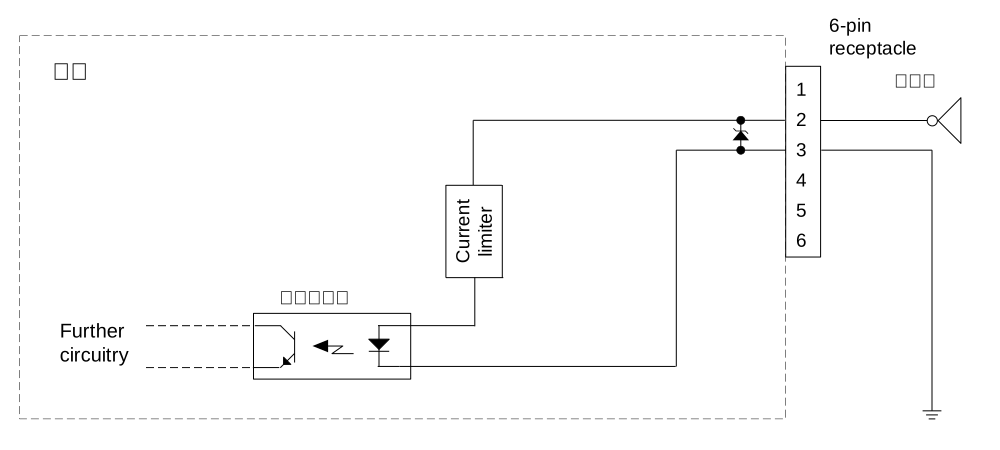
下图展示了使用光电耦合输入线路(Line 1)的典型电路。例如,在外部电路中使用 TTL 或 CMOS 逻辑门。
GPIO 输入线路#
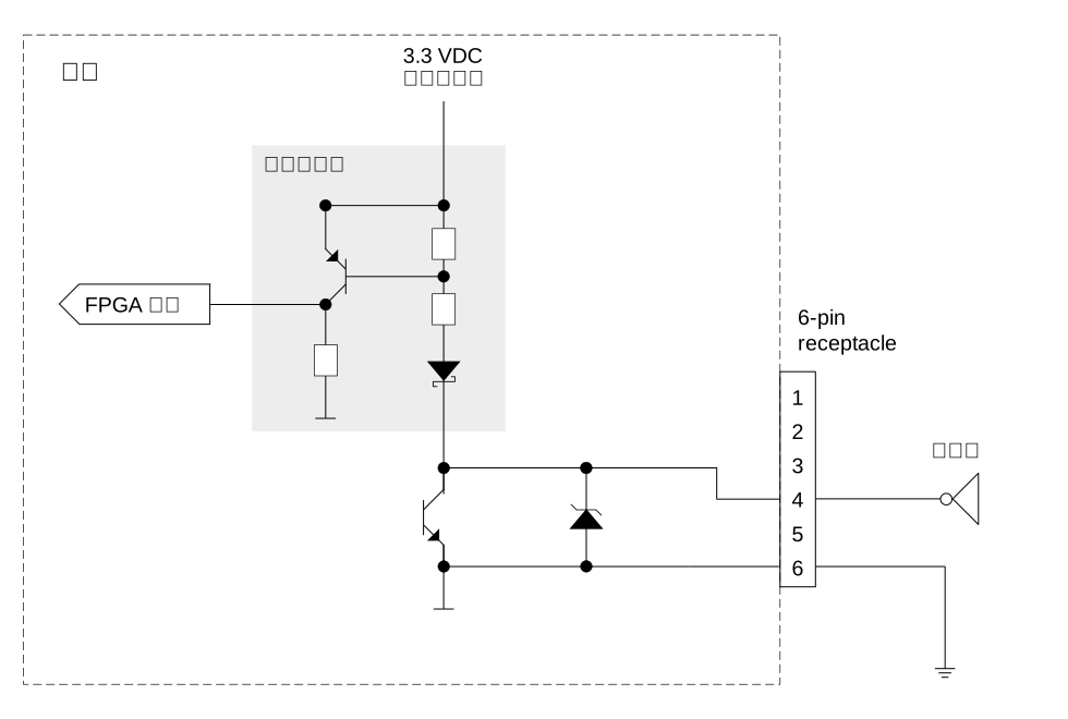
下图展示了将 GPIO 线路设置为输入线路时的典型电路。例如,已连接Line 2,并且在外部电路中使用了 TTL 或 CMOS 逻辑门。
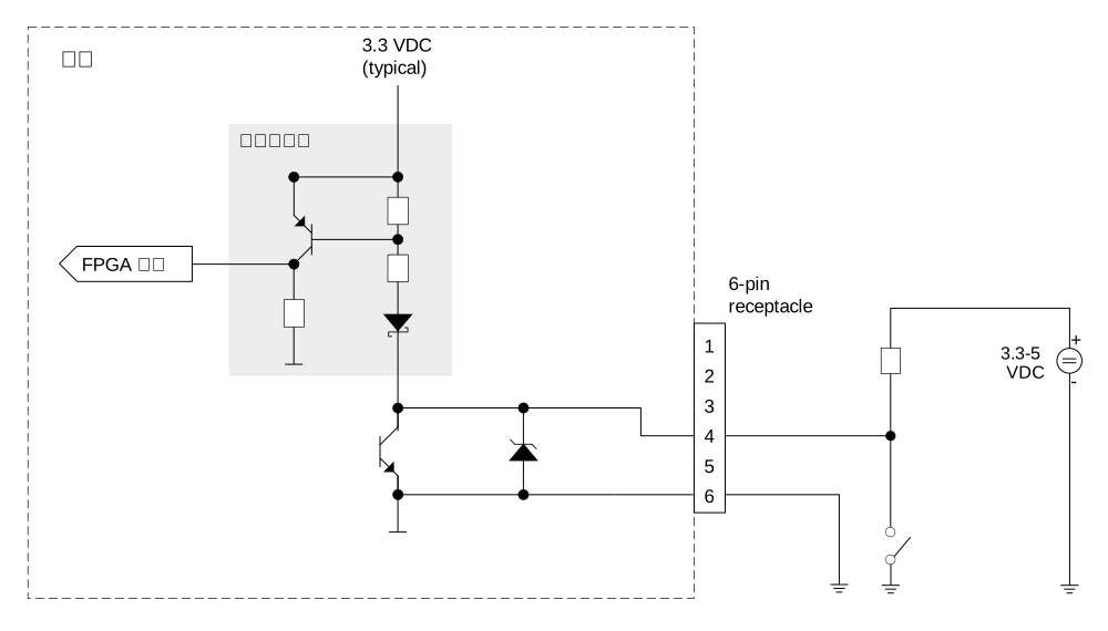
下图展示了使用 GPIO 线路的外部电路的另一个示例。
GPIO 输出线路#
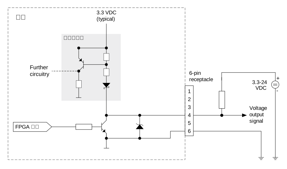
下图展示了将 GPIO 线路设置为用作输出线路时的典型电路。例如,已连接线路 2。此电路仅适用于接受 NPN 通信的设备。
boost V 相机#
电隔离输入线#
下图显示了使用电隔离输入线路(Line 1)的典型电路。外部电路中以 TTL 或 CMOS 逻辑门为例。输入脉冲必须长于 200 ns 才能被识别为信号。
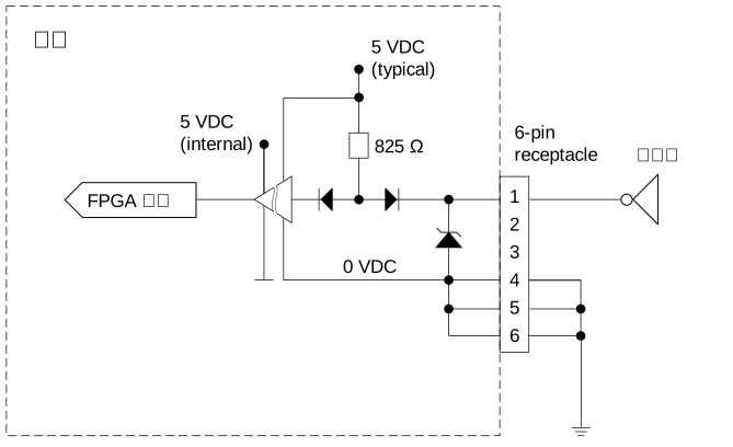
电隔离输出线#
下图显示了使用电隔离输出线路(Line 2)的典型电路。此电路仅适用于接受 NPN 通信的设备。
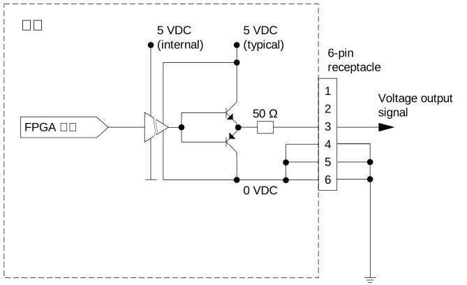
ace Classic/U/L 相机#
光电耦合输入线路#
下图展示了使用光电耦合输入线路的典型电路。例如,在外部电路中使用 TTL 或 CMOS 逻辑门。
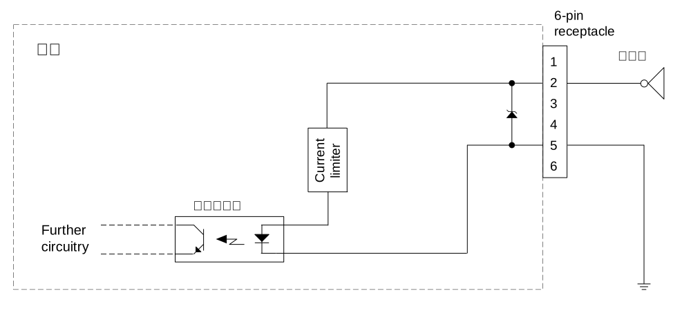
光电耦合输出线路#
下图展示了使用光电耦合输出线路的典型线路。此电路仅适用于接受 NPN 通信的设备。
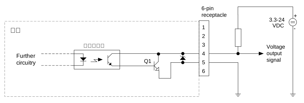
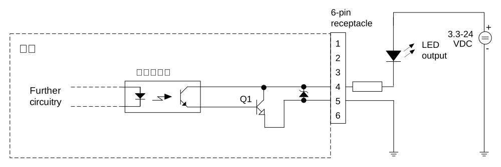
下图展示了可用于监视带 LED 的光电耦合输出线路的典型电路。在此示例中,外部电路中的电压为 24 VDC。电路中的电流受外部电阻限制。
GPIO 输入线路#
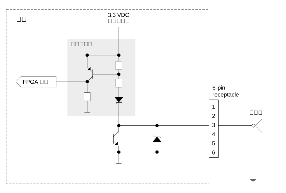
下图展示了将 GPIO 线路(如果您的相机型号中有此线路)设置为用作输入线路时的典型电路。例如,在外部电路中使用了 TTL 或 CMOS 逻辑门。
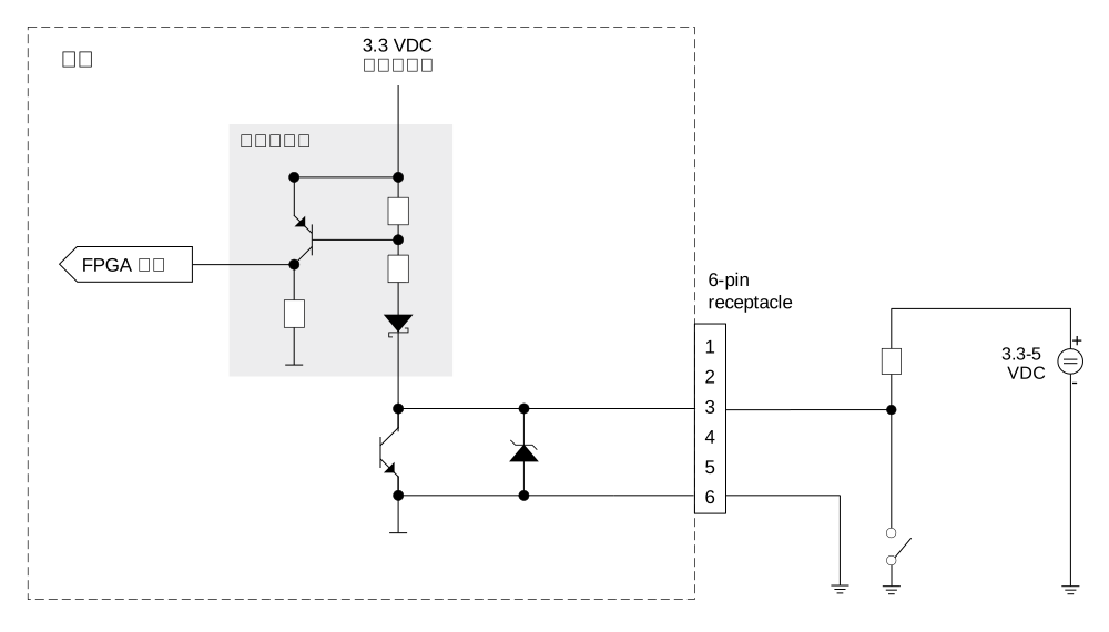
下图展示了使用 GPIO 线路(如果您的相机型号中有此线路)的外部电路的另一个示例。
GPIO 输出线路#
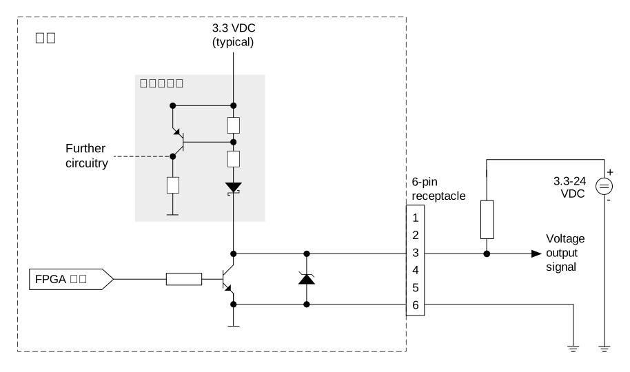
下图展示了将 GPIO 线路(如果您的相机型号中有此线路)设置为用作输出线路时的典型电路。此电路仅适用于接受 NPN 通信的设备。
dart Classic/R 相机#
GPIO 线路#
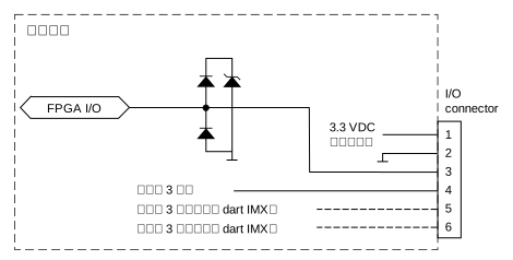
dart M 相机模块#
GPO 和 GPI 线路#
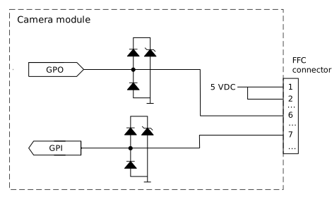
根据您与 dart M 相机模块一起使用的组件,另请参阅电路图(Basler dart M GigE 接口板)或电路图(Basler dart M GigE 交换机)。