应用说明:为可编程图像采集卡设计信号处理小应用程序#
VisualApplets 中的 GPI/GPO Operators#
使用 VisualApplets,您可以设计自己特定于应用程序的触发系统。例如,您可以决定由哪个单独的物理 I/O 引脚发送或接收哪个信号。
在 VisualApplets 中,您可以使用两个算子将单独的引脚连接到您的 applet 设计中:
算子 GPI(用于触发 IN 信号)
算子 GPO(用于触发 OUT 信号)
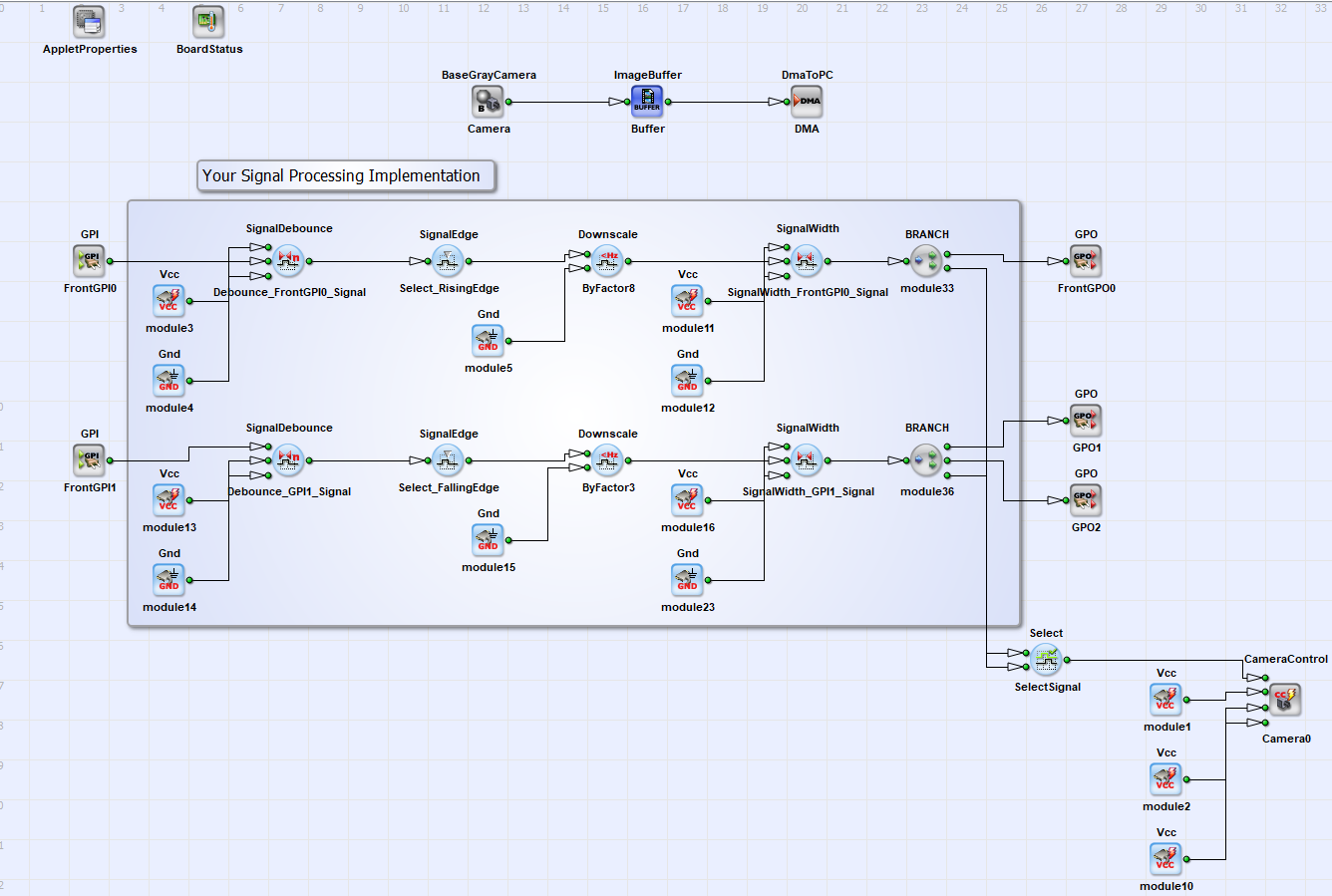
上图展示了一个如何实现信号处理的示例。您要实现的信号处理功能取决于您的具体需求。若要查找适合您应用的 operator,请访问 Signal Library。此外,请根据您的需求选择 Front GPIO。
上面的示例展示了针对两个输入信号的降采样功能。有两个信号从 GPI1 和 Front GPI0 输入到可编程采集卡。首先对信号进行去抖动处理,选择上升沿或下降沿,然后将信号按 8 或 3 的因子进行 Scaling。为两个信号设置信号长度,然后将信号转发到 FrontGPO0、GPO1、GPO2 以及相机以控制图像采集。
使用 GPI/GPO Operators#
您想要在 Front GPIO 或 Trigger Extension Board 上使用的每个触发 IN / 触发 OUT 引脚都必须与 GPI/GPO 算子的一个实例相互连接。
信息
由于算子 GPI 和算子 GPO 具有相同的功能,因此在下文中将对这两个算子进行联合描述。
- 双击设计中的 operator 图标以打开 Module Properties 窗口。
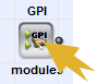
Module Properties 窗口打开:
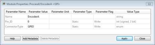
如您所见,该算子有两个参数:
Pin_ID:参数 Pin_ID 允许您定义要寻址所选连接器上的哪个单独引脚。ConnectorType:参数 ConnectorType 允许您定义要寻址哪个连接器(Front GPIO 或通过 GPIO 的 Trigger Extension Board)。
信息
对于 CXP-12 采集卡, ConnectorType 参数包含在 Pin_ID 参数。
Parameter Connector Type#
中。此参数允许您定义要寻址哪组触发引脚,即 15 针 D-Sub 插座中提供的引脚(Front GPIO),还是 Trigger Extension Board 上提供的引脚(GPIO)。该参数的值范围为 {Front GPIO, GPIO}。
值 Front GPIO#
如果您选择值 Front GPIO,则寻址可编程采集卡挡板上的以下连接器(触发引脚组):
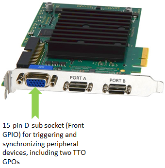
值 GPIO#
如果您选择值 GPIO,您将寻址可编程采集卡上的以下触发引脚组:
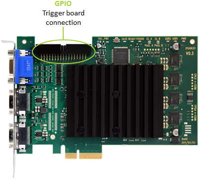
GPIO 用于连接 Trigger Extension Board:
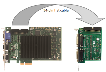
参数 Pin_ID#
此参数允许您定义要寻址所选连接器(触发引脚组)上的哪个单独引脚。参数的值范围 Pin_ID is {0;7} or {0;3} for connector type GPIO 或 Front GPIO.
信息
参数的值范围 Pin_ID for marathon frame grabbers and operator GPO is {0;1}.
结合 VisualApplets Operator 参考的 Front GPIO 引脚配置#
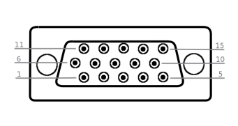
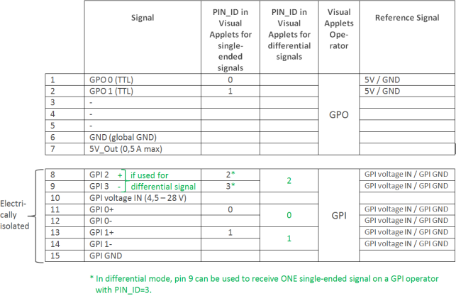
在差分模式下,引脚 9 可用于在具有 Pin_ID=3 的 GPI 算子上接收单个单端信号,请参见“差分”模式(默认)。
注意
采集卡的触发系统需要从 Voltage IN 引脚获取供电电压。如果您要连接没有 PWR 引脚的设备,则需要从外部电源为 Voltage IN 引脚提供电源。
Front GPIO 上的 Trigger INPUT#
如果您
- 正在使用
GPI运算符(用于定义触发输入信号), - 已将参数
Connector Type更改为Front GPIO,
参数的值 Pin_ID 请连接以下引脚:
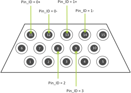
Front GPIO 的输入 (GPI) 引脚是可配置的。您可以使用六个输入引脚来接收以下信号之一:
- 3 个差分信号,或
- 2 个差分信号和 1 个单端信号,或
- 4 个单端信号。
要为特定信号类型(差分或单端)配置 Front GPIO 上的输入引脚,您有两种可用模式:
- 模式
Differential(提供选项 a 和 b) - 模式
Single-ended(提供选项 c)
Front GPIO 的默认模式为模式 Differential。有关如何切换模式的信息,请参阅主题 输入配置 在采集卡手册中。
注意
在默认配置下,Front GPIO 的 GPIO 引脚提供:
- 上拉模式下的 3 个差分输入信号,或 2 个差分和 1 个单端输入信号
- 两个 TTL 输出信号
如果您需要输入信号的其他配置,即:
- 下拉模式,
- 4 个单端信号(无差分信号),
您可以根据需要轻松配置 GPI。进行配置时,您需要使用随 Framegrabber SDK 一起安装在系统上的命令行工具。
模式 Differential (默认)#
在模式 Differential (默认值),Front GPIO 的所有六个输入引脚被配置为接收差分信号:
- 引脚 8/9 -> 1 个差分信号
- 引脚 11/12 -> 1 个差分信号
- 引脚 13/14 -> 1 个差分信号
或者,您可以使用引脚对 8/9(在模式 Differential下)来接收一个单端信号:
- 引脚 9 -> 1 个单端信号
- 引脚 11/12 -> 1 个差分信号
- 引脚 13/14 -> 1 个差分信号
模式下的单个引脚 Differential:
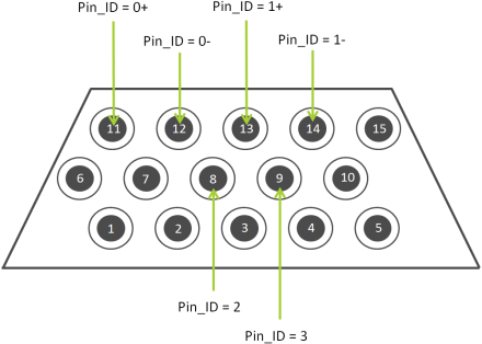
引脚 11 和 12:
- 引脚 11 和 12 上的输入信号被解释为一个差分信号(引脚 11 为正值,引脚 12 为负值)。
- 要在 VisualApplets 中接收此差分信号,请使用 Pin_ID = 0 的 GPI 算子实例。
引脚 13 和 14:
- 引脚 13 和 14 上的输入信号被解释为一个差分信号(引脚 13 为正值,引脚 14 为负值)。
- 要在 VisualApplets 中接收此差分信号,请使用 Pin_ID = 1 的 GPI 算子实例。
引脚 8 和 9:
- 引脚 8 和 9 上的输入信号被解释为一个差分信号(引脚 8 为正值,引脚 9 为负值)。
- 要在 VisualApplets 中接收此差分信号,请使用 Pin_ID = 2 的 GPI 算子实例。
或者,您可以使用引脚对 8/9 接收一个单端信号(尽管在模式 Differential下):在此情况下,
- 您将单端输入信号连接到物理引脚 9。
- 要在 VisualApplets 中接收此单端信号,请使用 Pin_ID = 3 的 GPI 算子实例。
模式 Single-Ended#
在模式 Single-ended (可配置),Front GPIO 的六个输入引脚被配置为接收 4 个单端信号:
- 引脚 8 -> 1 个单端信号
- 引脚 9 -> 1 个单端信号
- 引脚 11 -> 1 个单端信号
- 引脚 13 -> 1 个单端信号
模式下的单个引脚 Single-ended:
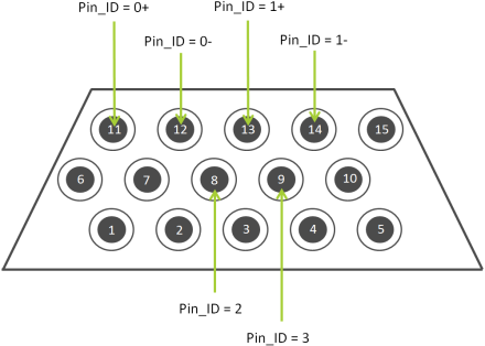
引脚 11 和 12 上的信号:
- 引脚 11 上的输入信号被解释为单端信号。
- 若要在 VisualApplets 中接收该单端信号,请使用 Pin_ID = 0 的 GPI 算子实例。
- 在以下模式中不使用引脚 12:
Single-ended.
引脚 13 和 14 上的信号:
- 引脚 13 上的输入信号被解释为单端信号。
- 若要在 VisualApplets 中接收该单端信号,请使用 Pin_ID = 1 的 GPI 算子实例。
- 在以下模式中不使用引脚 14:
Single-ended.
引脚 8 和 9:
- 引脚 8 和 9 上的输入信号被解释为两个单端信号。
-
若要在 VisualApplets 中接收这些单端信号,请使用
- 针对引脚 8 使用 Pin_ID = 2 的 GPI 算子实例,以及
- 针对引脚 9 使用 Pin_ID = 3 的 GPI 算子实例。
触发输出 TTL 位于 Front GPIO#
如果您
- 使用 GPO 算子定义触发输出信号,
- 您已将参数 Connector Type 设置为 Front GPIO,
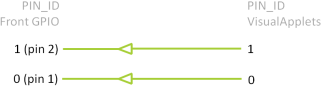
参数 Pin_ID 的值对应以下引脚:
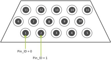
这两个引脚正在发送 TTL 信号(5 V)。
Front GPIO 上的传出 TTL 信号(5 V):
寻址 Trigger Extension Board 的触发信号(通过 GPIO)#
GPIO 接口是可编程采集卡的物理触发接口,专为连接 Trigger Extension Board 而设计:
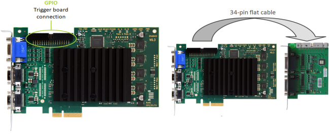
GPIO 接口(即每个 Trigger Extension Board)提供:
- 8 个数字输入(IN 0 - 7)(8 个单端信号或 4 个差分信号)
- 8 个数字输出(OUT 0 - 7)
这八个输入的索引为 0 到 7。这八个输出的索引也为 0 到 7。
有关引脚布局的更多信息,请参阅 Pin Layout on SUB-D15 - TTL Trigger Board 或 PIN Layout Opto-Coupled Trigger 5 - Opto-Coupled Trigger 5 Board 扩展板。
Pin_ID TTL Trigger Extension Board 上的分配#
Port A#
| 引脚编号 | Pin_ID 在 VisualApplets 中 |
|---|---|
| 1 | 0 |
| 2 | 1 |
| 3 | 2 |
| 4 | 3 |
| 5 | |
| 6 | |
| 7 | |
| 8 | |
| 9 | |
| 10 | |
| 11 | 0 |
| 12 | 1 |
| 13 | 2 |
| 14 | 3 |
| 15 | 0 |
Port B#
| 引脚编号 | Pin_ID 在 VisualApplets 中(单端信号) |
|---|---|
| 1 | 4 |
| 2 | 5 |
| 3 | 6 |
| 4 | 7 |
| 5 | |
| 6 | |
| 7 | |
| 8 | |
| 9 | |
| 10 | |
| 11 | 4 |
| 12 | 5 |
| 13 | 6 |
| 14 | 7 |
| 15 |
Pin_ID Opto Trigger 5 Extension Board 上的分配#
Port A#
| 引脚编号 | Pin_ID 在 VisualApplets 中(单端信号) | Pin_ID 在 VisualApplets 中(差分信号) |
|---|---|---|
| 1 | 0 | |
| 2 | 1 | |
| 3 | 2 | |
| 4 | 3 | |
| 5 | ||
| 6 | ||
| 7 | ||
| 8 | ||
| 9 | ||
| 10 | ||
| 11 | 0 | 0 |
| 12 | 1 | 0 |
| 13 | 2 | 2 |
| 14 | 3 | 2 |
| 15 |
Port B#
| 引脚编号 | Pin_ID 在 VisualApplets 中(单端信号) | Pin_ID 在 VisualApplets 中(差分信号) |
|---|---|---|
| 1 | 4 | |
| 2 | 5 | |
| 3 | 6 | |
| 4 | 7 | |
| 5 | ||
| 6 | ||
| 7 | ||
| 8 | ||
| 9 | ||
| 10 | ||
| 11 | 4 | 4 |
| 12 | 5 | 4 |
| 13 | 6 | 6 |
| 14 | 7 | 6 |
| 15 |
配置触发系统#
您可以通过以下两种方式访问触发配置:
- microDisplay X:在此处,您可以通过 GUI 输入触发参数值,以检查特定配置的结果。
- SDK:用于将采集卡编程接口实现到特定的图像处理软件应用程序中。
根据您的应用需求,对触发系统的要求也有所不同:
- 对于面阵扫描,只需要一种触发类型(帧触发)。
- 对于线阵扫描,需要两种触发类型:行触发(为每行发送一个触发脉冲)和帧触发。在线阵扫描应用中,帧触发控制图像中附加的行数。
您可以在此处找到有关如何触发面阵和线阵相机的更多信息。
信息
有关采集卡触发系统的更多信息,请参阅主题 GPIO Connectors。
信息
有关可用参数(以及特定设置可能产生的影响)的信息,请参考您正在使用的 applet 的文档。
在硬件上运行您的 Applet#
先决条件:
- 您的可编程采集卡已按照主题 Connecting Frame Grabbers 中的说明安装在您的系统上。
- Basler Framegrabber SDK 已按照 Installing the Framegrabber SDK 中的说明安装在您的系统上。
在可编程采集卡上运行 applet 之前,您必须将 *.hap 文件(applet)复制到宿主机 PC 上的 Basler Framegrabber SDK 安装目录中,并将其烧录到您的可编程采集卡上。
信息
烧录仅适用于 marathon 采集卡。
有关如何将 VisualApplets 设计转换为硬件 applet 的详细信息,请参阅 Hardware Applet: From Idea to Application。
-
将您在 VisualApplets 中构建的
*.hap文件复制到目录[Framegrabber SDK installation directory]/Hardware Applets/[frame grabber model]中。如果没有带有可编程采集卡型号名称的子目录,请创建一个。如果您在 VisualApplets 中使用了默认设置,您将找到您的*.hap位于您的 VisualApplets 安装目录下的子目录中的文件Designs. -
按照 Flashing 中的说明将 applet 安装到可编程采集卡上。
完成此操作后,您可以:
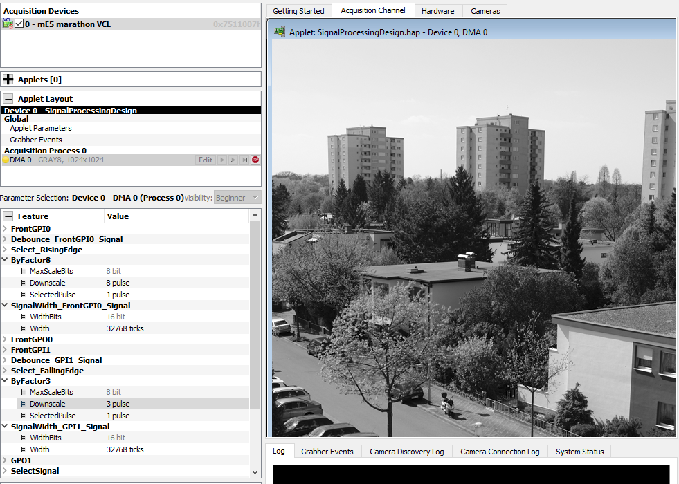
- 使用作为 Framegrabber SDK 一部分的 Basler 工具 microDisplay X 测试您的 applet 并直接查看 applet 的图像处理结果。请参阅主题 Configuring the Applet (microDisplay X)。
示例:当您将信号处理示例设计的硬件 applet 加载到 microDisplay X 中时,您可以在参数树中设置动态参数(如缩放因子和信号宽度),如下图所示。
在您自己的软件中启动 Applet#
若要开始在您自己的软件中使用该 applet:
- 在 Basler 应用程序编程接口上,使用调用
Fg_Init来启动 applet。指定您使用 VisualApplets 创建的*.hap文件的存放路径。
有关所有可用函数调用的详细说明和参考,请参阅 Framegrabber API Manual 和 Framegrabber API Function Reference。
作为 C++ SDK 的基础,您可以使用 VisualApplets 内部的 SDK 代码生成器,您可以在 VisualApplets 的图标菜单中找到它,或者在Build 和 Generate SDK example 下找到它。此函数会自动生成相应的 CMake 文件和 Visual Studio 项目文件(另请参阅 Hardware Applet: From Idea to Application)。
自动生成的 SDK 代码包含图像采集和参数配置所需以下功能块:
- 采集卡初始化
- 为缓冲区分配 Memory
- 定义
Get和Set参数 - 创建显示
- 针对每个存在的端口,在 applet 和相机上启动采集
- 抓取图像
- 停止采集
- 关闭显示
- 释放缓冲区的 Memory
- 采集卡反初始化
以下是针对信号处理示例的 C++ Framegrabber API 代码示例。
- 采集卡初始化和为缓冲区分配 Memory:
int main ()
{

    // ---------------------------------------------------------------------------
    // Frame Grabber: Initialization
    // ---------------------------------------------------------------------------


    int nrOfCycles = 5000; // Acquire 5000 frames, TODO: insert the number according to your needs
    unsigned int boardIndex = 0; // TODO: Use the correct board index at multi frame grabber systems
    int rc = 0; // return code

    Fg_Struct* fg = Fg_Init("SignalProcessingDesign.hap", boardIndex);
    if(fg == NULL){
        fprintf(stderr, "Error in Fg_Init(): %s\n", Fg_getLastErrorDescription(NULL));
        fprintf(stderr, "Press <Return> to continue...\n");
        getchar();
        return -1;
    }

    int nrOfParameter = Fg_getNrOfParameter(fg);
    fprintf(stderr, "No. of Parameter: %d\n", nrOfParameter);

    int i;
    for (i = 0; i < nrOfParameter; i++) {
        const char *name = Fg_getParameterName(fg,i);
        fprintf(stderr," Param %d: %s,%x\n",i,name,Fg_getParameterId(fg,i));
    }


    / ---------------------------------------------------------------------------
    // Frame Grabber: Allocate memory for buffer(s)
    // ---------------------------------------------------------------------------


    // Feature Cnt 0,0
    int width0 = 1024;
    int height0 = 1024;
    int byteWidth0 = 1;
    size_t bufSize0 = width0 * height0 * (size_t)byteWidth0;
    const unsigned int mem0_bufs = 4;
    dma_mem *pmem0 = Fg_AllocMemEx(fg, bufSize0 * mem0_bufs, mem0_bufs);
    if(pmem0 == NULL){
        fprintf(stderr, "Error in Fg_AllocMemEx(): %s\n", Fg_getLastErrorDescription(fg));
        Fg_FreeGrabber(fg);
        fg = NULL;
        fprintf(stderr, "Press <Return> to continue...\n");
        getchar();
        return -1;
    }
- 参数部分的
Get和Set摘录。此处展示了如何设置动态参数。以下代码展示了如何设置缩放因子以及如何选择特定脉冲作为运算符Device1_Process0_ByFactor8:
// ---------------------------------------------------------------------------
// Frame Grabber: Get* and Set* parameters for Process0
// ---------------------------------------------------------------------------


/*============ Downscale : ByFactor8 ============== */


int Device1_Process0_ByFactor8_Downscale_Id = Fg_getParameterIdByName(fg, "Device1_Process0_ByFactor8_Downscale");
if(Device1_Process0_ByFactor8_Downscale_Id <= 0) {
    fprintf(stderr, "\n");
    fprintf(stderr, "Error in Fg_getParameterIdByName(Device1_Process0_ByFactor8_Downscale): %s (%d)\n", Fg_getLastErrorDescription(fg), Device1_Process0_ByFactor8_Downscale_Id);
    fprintf(stderr, "Press <Return> to continue...\n");
    getchar();
}

unsigned int Device1_Process0_ByFactor8_Downscale;
Device1_Process0_ByFactor8_Downscale = 8;
rc = Fg_setParameterWithType(fg, Device1_Process0_ByFactor8_Downscale_Id, Device1_Process0_ByFactor8_Downscale, 0);
if(rc < 0) {
    fprintf(stderr, "\n");
    fprintf(stderr, "Error in Fg_setParameterWithType(Device1_Process0_ByFactor8_Downscale_Id): %s (%d)\n", Fg_getLastErrorDescription(fg), rc);
    fprintf(stderr, "Press <Return> to continue...\n");
    getchar();
}

int Device1_Process0_ByFactor8_SelectedPulse_Id = Fg_getParameterIdByName(fg, "Device1_Process0_ByFactor8_SelectedPulse");
if(Device1_Process0_ByFactor8_SelectedPulse_Id <= 0) {
    fprintf(stderr, "\n");
    fprintf(stderr, "Error in Fg_getParameterIdByName(Device1_Process0_ByFactor8_SelectedPulse): %s (%d)\n", Fg_getLastErrorDescription(fg), Device1_Process0_ByFactor8_SelectedPulse_Id);
    fprintf(stderr, "Press <Return> to continue...\n");
    getchar();
}

unsigned int Device1_Process0_ByFactor8_SelectedPulse;
Device1_Process0_ByFactor8_SelectedPulse = 1;
rc = Fg_setParameterWithType(fg, Device1_Process0_ByFactor8_SelectedPulse_Id, Device1_Process0_ByFactor8_SelectedPulse, 0);
if(rc < 0) {
    fprintf(stderr, "\n");
    fprintf(stderr, "Error in Fg_setParameterWithType(Device1_Process0_ByFactor8_SelectedPulse_Id): %s (%d)\n", Fg_getLastErrorDescription(fg), rc);
    fprintf(stderr, "Press <Return> to continue...\n");
    getchar();
}
信息
您可以从自动生成的 C++ Framegrabber API 代码中删除所有与采集期间参数设置无关的参数。只需保留采集期间需要配置的参数即可。
- 创建显示、开始采集并抓取图像:
// ---------------------------------------------------------------------------
// Frame Grabber: Create the display(s)
// ---------------------------------------------------------------------------

int id0 = CreateDisplay(8 * byteWidth0, width0, height0);
if(id0 < 0) {
    fprintf(stderr, "Error in CreateDisplay(): %s (%d)\n", Fg_getLastErrorDescription(fg), id0);
    Fg_FreeMemEx(fg, pmem0);
    pmem0 = NULL;
    Fg_FreeGrabber(fg);
    fg = NULL;
    fprintf(stderr, "Press <Return> to continue...\n");
    getchar();
    return id0;
}
SetBufferWidth(id0, width0, height0);


// ---------------------------------------------------------------------------
// Frame Grabber: Start acquisition at applet and camera for each present port
// ---------------------------------------------------------------------------

rc = Fg_AcquireEx(fg, 0, nrOfCycles, ACQ_STANDARD, pmem0);
if(rc != 0) {
    fprintf(stderr, "Error in Fg_AcquireEx() for channel 0: %s\n", Fg_getErrorDescription(fg, rc));
    CloseDisplay(id0);
    Fg_FreeMemEx(fg, pmem0);
    pmem0 = NULL;
    Fg_FreeGrabber(fg);
    fg = NULL;
    fprintf(stderr, "Press <Return> to continue...\n");
    getchar();
    return rc;
}

// ---------------------------------------------------------------------------
// Frame Grabber: Grab images
// ---------------------------------------------------------------------------

frameindex_t frameNo0 = 0;
for(i = 1; i <= nrOfCycles; ++i){
frameNo0 = Fg_getLastPicNumberBlockingEx(fg, frameNo0 + 1, 0, 5, pmem0);
    if(frameNo0 < 0) {
        fprintf(stderr, "Error in Fg_getLastPicNumberBlockingEx(): %s (%d)\n", Fg_getLastErrorDescription(fg), frameNo0);
        fprintf(stderr, "Press <Return> to continue...\n");
        getchar();
        break;
    } else {
        fprintf(stderr, "grabbed image %d\n", frameNo0 );
    }

    void *iPtr0 = Fg_getImagePtrEx(fg, frameNo0, 0, pmem0);
    if(iPtr0 == NULL) {
        fprintf(stderr, "Error in Fg_getImagePtrEx(): %s\n", Fg_getLastErrorDescription(fg));
        Fg_stopAcquireEx(fg, 0, pmem0, 0);
        CloseDisplay(id0);
        Fg_FreeMemEx(fg, pmem0);
        pmem0 = NULL;
        Fg_FreeGrabber(fg);
        fg = NULL;
        fprintf(stderr, "Press <Return> to continue...\n");
        getchar();
        return -1;
    }
    DrawBuffer(id0, iPtr0, frameNo0, "");
}
- 停止采集、关闭显示、释放缓冲区内存:
// ---------------------------------------------------------------------------
// Frame Grabber: Stop acquisition
// ---------------------------------------------------------------------------

rc = Fg_stopAcquireEx(fg, 0, pmem0, 0);
if(rc < 0) {
    fprintf(stderr, "Error in Fg_stopAcquireEx(): %s (%d)\n", Fg_getLastErrorDescription(fg), rc);
    fprintf(stderr, "Press <Return> to continue...\n");
    getchar();
}


// ---------------------------------------------------------------------------
// Frame Grabber: Close the display
// ---------------------------------------------------------------------------

CloseDisplay(id0);


// ---------------------------------------------------------------------------
// Frame Grabber: Release the memory for buffer(s)
// ---------------------------------------------------------------------------

rc = Fg_FreeMemEx(fg, pmem0);
if(rc < 0) {
    fprintf(stderr, "Error in Fg_FreeMemEx(): %s (%d)\n", Fg_getLastErrorDescription(fg), rc);
    fprintf(stderr, "Press <Return> to continue...\n");
    getchar();
}
pmem0 = NULL;


// ---------------------------------------------------------------------------
// Frame Grabber: Uninitialization
// ---------------------------------------------------------------------------

rc = Fg_FreeGrabber(fg);
if(rc < 0) {
    fprintf(stderr, "Error in Fg_FreeGrabber(): %s\n", Fg_getLastErrorDescription(NULL));
    fprintf(stderr, "Press <Return> to continue...\n");
    getchar();
}
fg = NULL;


fprintf(stderr, "Press <Return> to exit...\n");
getchar();

return (0);
}
您可以将此示例代码集成到更大的 SDK 环境中。