Opto-Coupled Trigger 5#
It offers 16 opto-coupled (galvanically isolated) trigger signals for controlling cameras and peripheral devices. Its signals can be adapted to the industrial signal level (typically 5–24 VDC).
Using the board, you can synchronize multiple frame grabbers. It is configurable and can replace any of the six variants of its predecessor Basler OPTO trigger board IV.
Info
The Opto-Coupled Trigger 5 board is a hardware extension that must be purchased separately. For availability and pricing, see the product page on the Basler website.
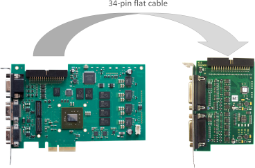
The board can be connected to a frame grabber via a 34-pin flat cable:
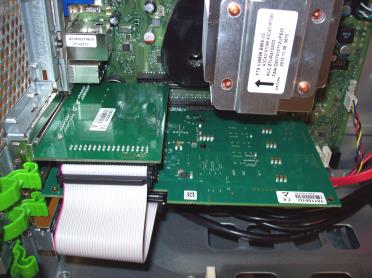
The following image shows the board installed in a computer:
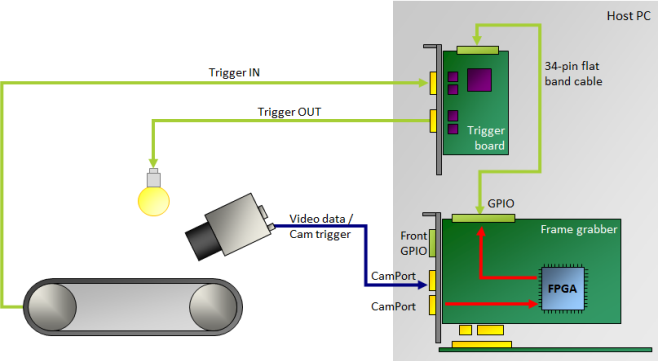
The following image shows an example of a production line using the Opto-Coupled Trigger 5 board:
Info
You can configure the individual I/Os of the trigger extension board using applets. Refer to the documentation of your specific applet.
Package Contents#
The following items are included in the package:
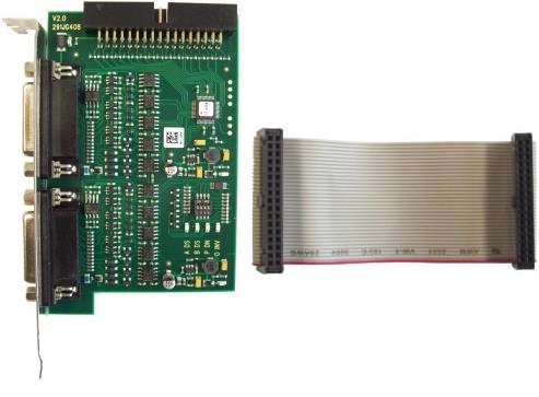
- Opto-Coupled Trigger 5 board (order number 2200000371)
- 34-pin flat cable for connecting the trigger board to the frame grabber
Info
- You can order additional equipment, such as a 34-pin flat cables for multi-board installation, directly from Basler.
- To connect to multiple trigger boards, Basler recommends using a specific 34-pin flat cable provided by Basler, the "Multi-Board Trigger Cable". It offers a connector for the trigger board and multiple connectors for Opto-Coupled Trigger 5 devices. The signals of the cable use open collector drivers.
The Multi-Board Trigger Cable is available in two variants:- Multi-Board Trigger Cable – Left (order number 2200000374)
- Multi-Board Trigger Cable – Right (order number 2200000480)
Contact Basler Sales for additional ordering information.
Ports and LEDs#
The following ports and LEDs are available on the board:
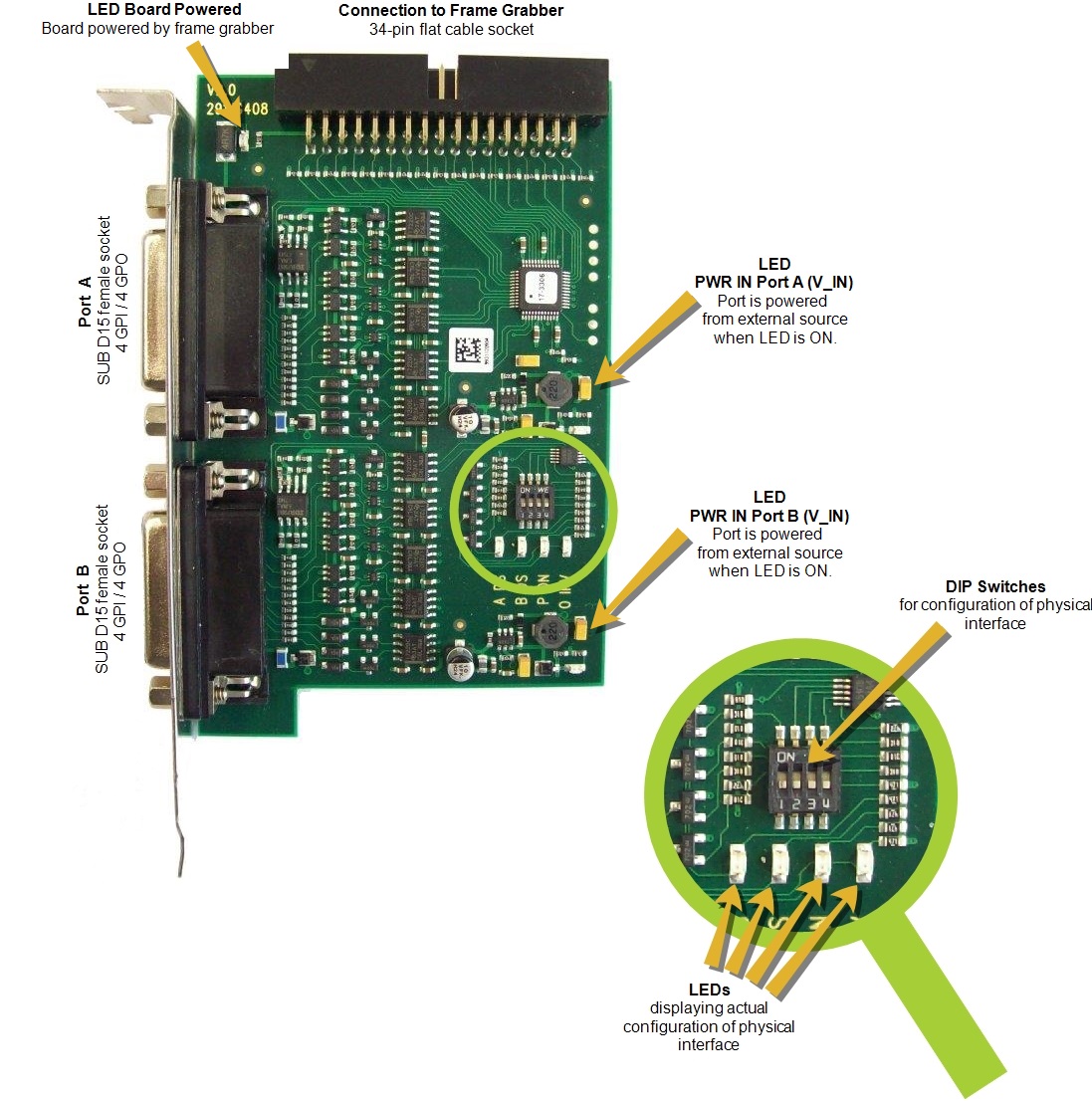
The GPIs and GPOs are mapped to two ports, port A and port B:

The board offers 8 inputs and 8 outputs on its two female SUB-D 15 sockets:
| Port A | Port B |
|---|---|
4 inputs  | 4 inputs  |
4 outputs  | 4 outputs  |
You can configure various parameters that allow you to use the board in different operation modes:
- You can configure the IN pins of port A to receive single-ended or differential incoming signals.
- You can configure the IN pins of port B to receive single-ended or differential incoming signals.
- You can configure whether you want to use the IN pins in pull-up or pull-down mode.
- You can configure whether the outgoing signals are inverted or not.
For details on configuring the board, refer to the Configuring the Physical Interface section.
For information which signals are received by the board via the flat cable, see Flat Cable Pinout.
PIN Layout Opto-Coupled Trigger 5#
All GPIs and GPOs available on the board are mapped to the two SUB D15 sockets (Port A and Port B). They have the following indices:
| Port A | Port B |
|---|---|
4 IN port A (indices 0–3)  | 4 IN port B (indices 4–7)  |
4 OUT port A (indices 0–3)  | 4 OUT port B (indices 4–7)  |
| Pin Number | 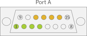 Signal Name | 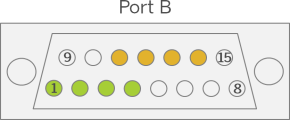 Signal Name |
|---|---|---|
| 1 | Trigger Output 0 Port A | Trigger Output 4 Port B |
| 2 | Trigger Output 1 Port A | Trigger Output 5 Port B |
| 3 | Trigger Output 2 Port A | Trigger Output 6 Port B |
| 4 | Trigger Output 3 Port A | Trigger Output 7 Port B |
| 5 | V_IN (VCC Input Port A) | V_IN (VCC Input Port B) |
| 6 | GND Port A | GND Port B |
| 7 | nc | nc |
| 8 | nc | nc |
| 9 | nc | nc |
| 10 | V_IN (VCC Input Port A) | V_IN (VCC Input Port B) |
| 11 | Trigger Input 0 Port A (+ if used for diff. signal) | Trigger Input 4 Port B (+ if used for diff. signal) |
| 12 | Trigger Input 1 Port A (- if used for diff. signal) | Trigger Input 5 Port B (- if used for diff. signal) |
| 13 | Trigger Input 2 Port A (+ if used for diff. signal) | Trigger Input 6 Port B (+ if used for diff. signal) |
| 14 | Trigger Input 3 Port A (- if used for diff. signal) | Trigger Input 7 Port B (- if used for diff. signal) |
| 15 | GND Port A | GND Port B |
Info
- The power must be delivered by an external power source.
- The input signals aren't passed directly to the opto-couplers but sent to differential comparators. This has the benefit that the input can accept low current, voltage driven signals between 5 and 25 VDC. (Input signals can have pull-up or pull-down resistor of 10 kΩ.) The polarity of the input signals is not inverted.
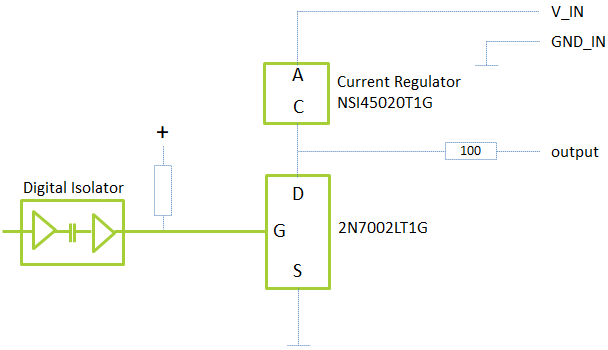
- On Opto-Coupled Trigger 5 boards, the opto-couplers don't connect directly to the output, but are buffered by MOSFET transistors. These transistors build an easy-to-use open collector driver with a 20 mA static current diode as pull-up.
Configuring the Physical Interface#
You can configure various parameters that allow you to use the Opto-Coupled Trigger 5 board in different operation modes:
- You can configure the IN pins of port A to receive single-ended or differential signals.
- You can configure the IN pins of port B to receive single-ended or differential signals.
- You can configure whether the IN pins of both ports should operate in pull-up or pull-down mode.
- You can configure whether outgoing signals are inverted or not.
You set the individual parameters via the DIP switches located directly on the trigger board.
Info
When using a microEnable 5 marathon frame grabber, you can change the configuration using the gpiotool command line tool. Configuration by software overrides the DIP switch setting.
The LEDs on the board inform you which settings are active.
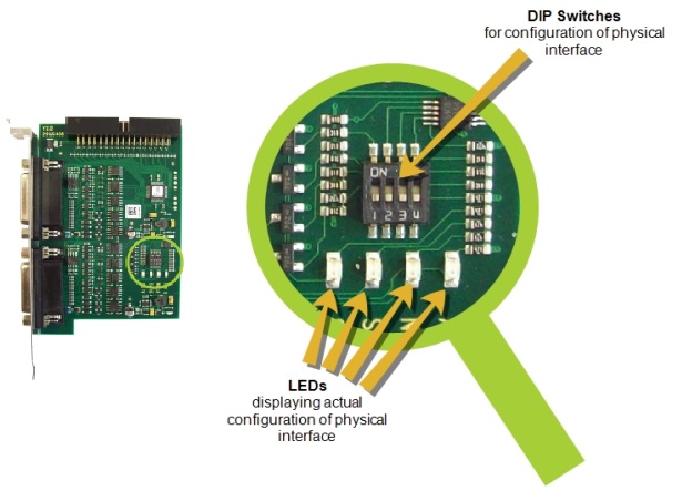
Info
The software configuration always overrides the position of the DIP switches. Therefore, the position of the DIP switches on the board may not represent the actual setting. To know which settings are active, always rely on the LEDs.
Default Settings#
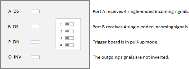
At delivery, the default settings are active. All DIP switches and all LEDs on the Opto-Coupled Trigger 5 board are set to Off.
The default settings for the Opto-Coupled Trigger 5 board are as follows:
- Port A receives four single-ended incoming signals.
- Port B receives four single-ended incoming signals.
- The trigger board is in pull-up mode.
- The outgoing signals aren't inverted.
By default, the four LEDs are set to Off:
Single Ended / Differential IN Signals#
You can configure the IN pins of the Opto-Coupled Trigger 5 board as follows:
-
All IN pins of port A and B receive single ended inputs (= 8 single-ended IN signals):
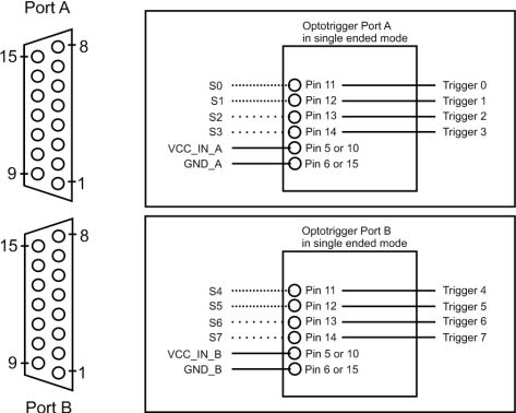
This is the default setting. The DIP switches for port A (switch 1) and port B (switch 2) are in Off position. The LEDs for port A (A DS) and port B (B DS) are off:
 2. All IN pins of port A and B receive differential inputs (= 4 differential IN signals, i.e., 4 pairs):
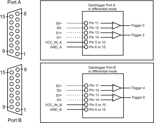
The DIP switches for port A (switch 1) and port B (switch 2) are in On position. The LEDs for port A (A DS) and B (B DS) are on:
 3. All IN pins of port A receive single-ended inputs, all IN pins of port B receive differential inputs (= four single-ended IN signals on A + two differential signals on B):
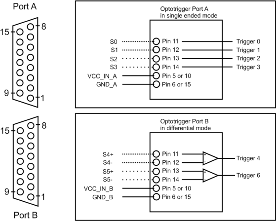
The DIP switch for port A (switch 1) is in Off position. The LED for port A (A DS) is off. The DIP switch for port B (switch 2) is in On position. The LED for port B (B DS) is on:

-
All IN pins of port A receive differential inputs, all IN pins of port B receive single-ended inputs (= two differential signals on A + four single-ended IN signals on B):
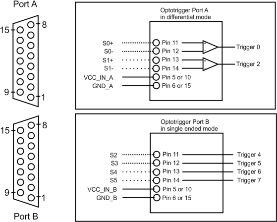
The DIP switch for port A (switch 1) is in On position. The LED for port A (A DS) is on. The DIP switch for port B (switch 2) is in Off position. The LED for port B (B DS) is off:

Pull Up / Pull Down#
You can configure the Opto-Coupled Trigger 5 board according to the electrical source of the incoming signal:
- Use pull-up (10 kΩ) to receive signals from NPN transistors (open collector, open drain).
- Use pull-down (10 kΩ) to receive signals from PNP transistors (open emitter, open source).
In most application scenarios, you should configure the Opto-Coupled Trigger 5 board to pull-up.
-
Pull-up: This is the default setting. The DIP switch for transistor mode (switch 3) is in Off position. The LED P DN is off:

-
Pull-Down: The DIP switch for transistor mode (switch 3) is in Off position. The LED P DN is off:

Inverted OUT Signals#
You can configure the OUT pins of the trigger board to invert the outgoing trigger signals.
All high (1) signals are converted to low (0) signals and vice versa.
-
Not Inverted: This is the default setting. The DIP switch for inversion (switch 4) is in Off position. The LED O INV is off:

-
Inverted: The DIP switch for inversion (switch 4) is in On position. The LED O INV is on:

Configuration via Software#
If you use the Opto-Coupled Trigger 5 board with a marathon frame grabber, you can also use software to configure the physical interface of the Opto-Coupled Trigger 5 board.
When you configure the Opto-Coupled Trigger 5 board via software, the position of the DIP switches doesn't provide any information about the actual configuration.
However, the LEDs on the Opto-Coupled Trigger 5 board always inform you which setting is active. In addition, you can use the software to get information about the current settings.
Info
- You can reset a board to the current DIP switch settings. This overrides the software configuration. For more information, see gpioTool.
- When the Opto-Coupled Trigger 5 board has been configured via software, the O INV LED may appear less bright than the other LEDs. This is a known issue and has no impact on functionality.
Configuration via Command Line#
To configure the physical interface of the Opto-Coupled Trigger 5 board via command line, use the gpioTool command line tool.
LED Status#
| LED Label | LED not active | LED active |
|---|---|---|
| A DS | Port A receives 4 single-ended incoming signals. | Port A receives 2 differential incoming signals. |
| B DS | Port B receives 4 single-ended incoming signals. | Port B receives 2 differential incoming signals. |
| P DN | The trigger board is in pull-up mode. | The trigger board is in pull-down mode. |
| O INV | The outgoing signals aren't inverted. | The outgoing signals are inverted. |
Info
The LEDs always show the actual configuration, regardless of whether it was made via DIP switches or via software.
Electrical Characteristics#
There are three power and ground systems on the Opto-Coupled Trigger 5 board. One supplies the signals of the port A connector, another one the signals of the port B connector, and the third one the signals of the flat cable connector. There is no electrical connection between these three systems.
Each of the systems may have a different supply voltage. The voltage range is between 5 and 25.0 VDC. The signal voltage is defined by the supply voltage for both input and output. See below for details on the electrical characteristics.
The following information applies to the physical input and output ports of both ports A and B.
Inputs#
| Min | Typical | Max | Unit | |
|---|---|---|---|---|
| Supply Voltage | 4.5 VDC | 28 VDC | V | |
| Input Threshold | 20% supply voltage | V | ||
| Differential Input Offset Voltage | 10 mV | mV | ||
| Input Current | 4 | mA (per channel) |
Info
- The input signals aren't passed directly to the opto-couplers but sent to differential comparators. This has the benefit that the input can accept low current, voltage driven signals between 5 and 25 VDC. (Input signals can have pull-up or pull-down resistor of 10 kΩ.) The polarity of the input signals is not inverted.
- The board has been designed with a varistor which opens at an input voltage of 30 VDC to let the onboard surge protector get active to protect the board. At a total supply voltage of 36 VDC, the electronic chips will become defective.
Outputs#
| Min | Typical | Max | Unit | |
|---|---|---|---|---|
| Supply Voltage (Max. Supply Current per Port) | 4.5 VDC | 28 VDC | V | |
| Output Signal Voltage High | -0.3 VDC Supply Voltage | V | ||
| Output Signal Voltage Low | 0.3 | mV | ||
| Output Current | 20 | mA (per channel) |
The supply current required for each port of the Opto-Coupled Trigger 5 board depends on the number of used inputs and outputs, the signal and the voltage level. Typical supply current required per port: < 200 mA/port
Info
- On Opto-Coupled Trigger 5 boards, the opto-couplers don't directly connect to the output, but are buffered by MOSFET transistors. These transistors build an easy-to-use open collector driver with a 20 mA static current diode as pull-up. Note that the power must be delivered by the external power source.
- The board has been designed with a varistor which opens at an input voltage of 30 VDC to let the onboard surge protector get active to protect the board. At a total supply voltage of 36 VDC, the electronic chips will become defective.
Timing Characteristics#
Inputs#
| Min | Typical | Max | Unit | |
|---|---|---|---|---|
| Propagation Delay | 200 | 230 | 260 | ns |
| Min. Pulse Width | 200 | ns | ||
| Max. Frequency (50% Duty Cycle) | 2.5 | MHz |
Outputs#
| Min | Typical | Max | Unit | |
|---|---|---|---|---|
| Propagation Delay | 40 | 60 | 80 | ns |
| Min. Pulse Width | 200 | ns | ||
| Max. Frequency (50% Duty Cycle) | 2.5 | MHz |
Because a static current diode is used as a pull-up of the output signal, there is a static rise time that leads to different low-high transition delays for different voltages and loads. The delay time is measured without load from and to 50 % of the signal level.
Schematic Drawings#
Input Circuits#
Port A#
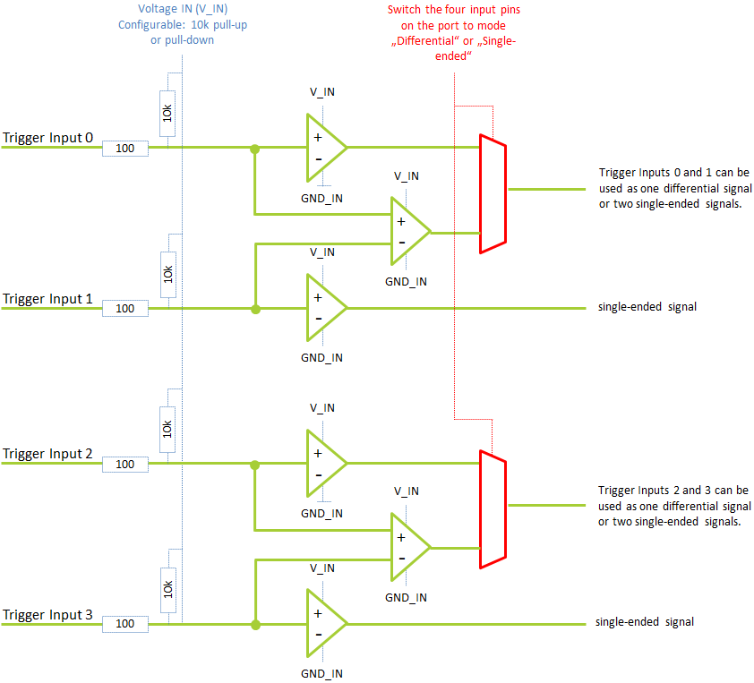
Port A offers the trigger inputs 0, 1, 2, and 3. Voltage IN (V_IN) and Ground (GND_IN) are galvanically isolated from the host computer:
Port B#
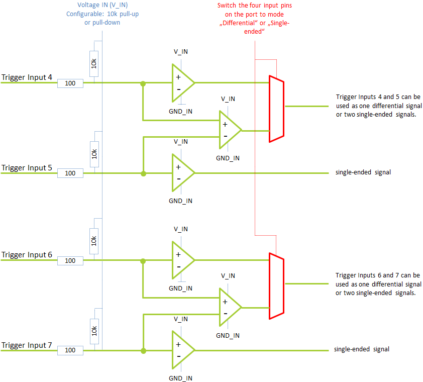
Port B offers the trigger inputs 4, 5, 6, and 7. Voltage IN (V_IN) and Ground (GND_IN) are galvanically isolated from the host computer:
Output Circuits#
Voltage IN (V_IN) and ground IN (GND_IN) are galvanically isolated from the host computer:
Appendix#
Flat Cable Pinout#

Odd Pin Numbers
| Pin Number | I/O Name |
|---|---|
| 1 | Trigger Output 0 |
| 3 | Trigger Output 1 |
| 5 | Trigger Output 2 |
| 7 | Trigger Output 3 |
| 9 | Trigger Input 0 |
| 11 | Trigger Input 1 |
| 13 | Trigger Input 2 |
| 15 | Trigger Input 3 |
| 17 | Trigger Output 4 |
| 19 | Trigger Output 5 |
| 21 | Trigger Output 6 |
| 23 | Trigger Output 7 |
| 25 | Trigger Input 4 |
| 27 | Trigger Input 5 |
| 29 | Trigger Input 6 |
| 31 | Trigger Input 7 |
| 33 | Presence Detect |
Even Pin Numbers
| Pin Number | I/O Name |
|---|---|
| 2 | +3.3 VDC |
| 4 | +3.3 VDC |
| 6 | GND |
| 8 | GND |
| 10 | GND |
| 12 | GND |
| 14 | GND |
| 16 | GND |
| 18 | GND |
| 20 | GND |
| 22 | GND |
| 24 | GND |
| 26 | GND |
| 28 | GND |
| 30 | GND |
| 32 | VCCIO (+2.5 VDC / 3.3 VDC) |
| 34 | VCCIO (+2.5 VDC / 3.3 VDC) |