GPIO Connectors#
This allows you to set up a detailed and complex trigger system, including:
- Receive trigger signals from external devices like Shaft Encoders, light barriers, etc. (trigger IN).
- Send trigger signals from the frame grabber to external devices like camera, lighting, etc. (trigger OUT)
- Receive software triggers.
Info
The triggers of the imaFlex CXP-12 Penta frame grabber can only be configured via applets, not via the trigger and GPIO options described here. However, you can configure the trigger via any applet. For detailed information, refer to the following documentation:
- VisualApplets documentation, specifically, the AppletProperties Operator Documentation
- The Application Note: Designing Signal Processing Applets for Programmable Frame Grabbers
- Chapter Miscellaneous/GPIO Configuration of your standard applet documentation for imaFlex CXP-12 Penta
Info
Programmable frame grabbers (i.e., imaFlex CXP-12 Quad, marathon VCX-QP, marathon VLC, and marathon VLCx): In addition to the trigger and GPIO options described here, you can also develop your own trigger system using VisualApplets. For detailed information, refer to the following documentation:
- VisualApplets documentation, specifically, the AppletProperties Operator Documentation
- The Application Note: Designing Signal Processing Applets for Programmable Frame Grabbers
By using triggers, you are able to control the image acquisition process. You can, for example, acquire an image at a particular moment in time, define when to accept an image delivered by the camera, specify how many lines should be acquired, or control the lighting.
Trigger Interfaces on Basler Frame Grabbers#
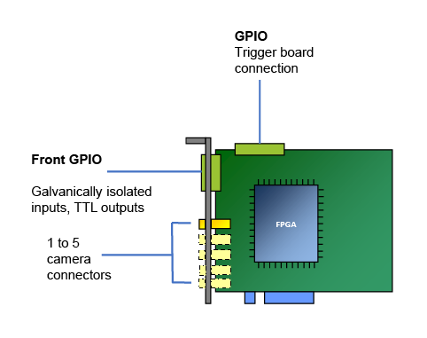
Basler frame grabbers offers the following trigger interfaces:
- One 15-pin D-Sub Micro-D connector (trigger unit "Front GPIO" on the slot bracket).
- One 34-pin socket (trigger unit "GPIO") for connecting an additional trigger board (Opto Trigger 5 or TTL Trigger).
- Two software triggers (A and B).
- marathon ACL, marathon VCL, and marathon VCLx: Four camera control signals (CC signals) per Camera Link port for controlling the camera.
On imaFlex CXP-12 Penta, imaFlex CXP-12 Quad, marathon VCX-QP, marathon VCL, and marathon VCLx, you can configure the individual pins of the Front GPIO and the trigger extension board as well as the software triggers (and for all CL frame grabbers: CC signals) with VisualApplets.
Input Configuration#
For GPI configuration, you have two signal modes available: "Differential" and "Single-ended". "Differential" is the default mode.
- In Differential mode, you can use the GPIs on the Front GPIO for receiving either up to 3 differential signals, or for receiving two differential signals and one single-ended signal.
- In Single-ended mode, you can use the GPIs on the Front GPIO for receiving up to 4 single-ended signals.
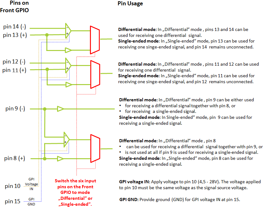
You can switch between modes using the gpioTool command line tool.
Info
The gpioTool doesn't work for the imaFlex CXP-12 Penta frame grabber. The triggers of the imaFlex CXP-12 Penta frame grabber can only be configured via applets. However, you can configure the trigger via any applet. For detailed information, refer to the following documentation:
- VisualApplets documentation, specifically, the AppletProperties Operator Documentation
- The Application Note: Designing Signal Processing Applets for Programmable Frame Grabbers
- Chapter Miscellaneous/GPIO Configuration of your standard applet documentation for imaFlex CXP-12 Penta
Differential Mode#
In the default "Differential" mode, all the six input pins of the Front GPIO are configured to receive differential signals (in pull-up mode):
| Pin # | Signal |
|---|---|
| 8/9 | 1 differential signal (pin 8+, pin 9- ) |
| 11/12 | 1 differential signal (pin 11+, pin 12-) |
| 13/14 | 1 differential signal (pin 13+, pin 14-) |
| 10 | GPI voltage IN (4.5–28 VDC): The GPI voltage IN must be the same voltage as the signal source voltage. |
| 15 | GPI GND |
Alternatively, you can use pin pair 8/9 to receive one single-ended signal. To do so, you connect the single-ended incoming signal to physical pin 9. Pin 8 isn't connected.
Single-Ended Mode#
If you need more than one single-ended input signal, you can switch the GPIs of your Front GPIO into "Single-ended" mode. In "Single-ended" mode, the six input pins of the Front GPIO are configured to receive four single-ended signals:
| Pin # | Signal |
|---|---|
| 8 | 1 single-ended signal |
| 9 | 1 single-ended signal |
| 11 | 1 single-ended signal (pin 12 not used) |
| 13 | 1 single-ended signal (pin 14 not used) |
| 10 | GPI voltage IN (4.5–28 VDC): The GPI voltage IN must be the same voltage as the signal source voltage. |
| 15 | GPI GND |
You can switch between "Single-ended" and "Differential" mode using the gpioTool command line tool.
Info
Both configurations (Differential and Single-ended) can be used in pull-up and pull-down mode. Pull-up mode is the default. If you want to use the inputs in pull-down mode, you can configure the pins accordingly using the gpioTool command line tool.
Front GPIO#
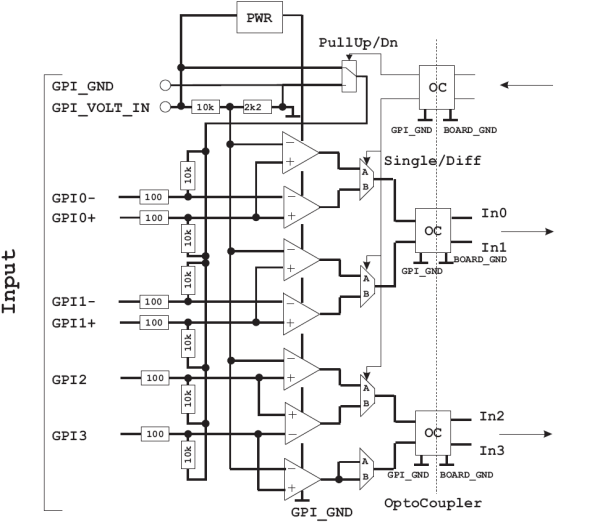
Schematic Circuit Diagram Front GPIO for All Frame Grabbers Except imaFlex CXP-12 Penta#
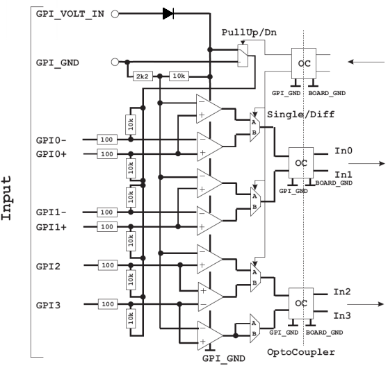
Schematic Circuit Diagram Front GPIO for imaFlex CXP-12 Penta#
Electrical Characteristics of the Physical Inputs#
| Description | Minimum | Typical | Maximum | Unit |
|---|---|---|---|---|
| Supply voltage | 4.5 | 28 | VDC | |
| Input threshold | 20% Supply Voltage | VDC | ||
| Differential input offset voltage | 10 | mV | ||
| Current at GPI pin | 4 | mA | ||
| Total current at GPI voltage IN | 50 | mA |
Timing Characteristics of the Physical Inputs#
| Timing | Minimum | Typical | Maximum | Unit |
|---|---|---|---|---|
| Propagation delay | 40 | 60 | 80 | ns |
| Min. pulse width | 200 | ns | ||
| Max. frequency | 2.5 | MHz |
Info
Basler frame grabbers are equipped with a varistor that opens at an input voltage of 30 VDC (on the GPIOs). This activates the onboard surge protector to protect the board. At a total supply voltage of 36 VDC, electronics would become defective.
Trigger Output TTL#
Schematic Circuit Diagram for all Frame Grabbers Except imaFlex CXP-12 Penta#
For all frame grabbers except imaFlex CXP-12 Penta, pins 1 and 2 can be used to send TTL trigger output signals (5 VDC).

Schematic Circuit Diagram for imaFlex CXP-12 Penta#
For imaFlex CXP-12 Penta, pins 1, 2, 3 and 4 can be used to send TTL trigger output signals (5 VDC).
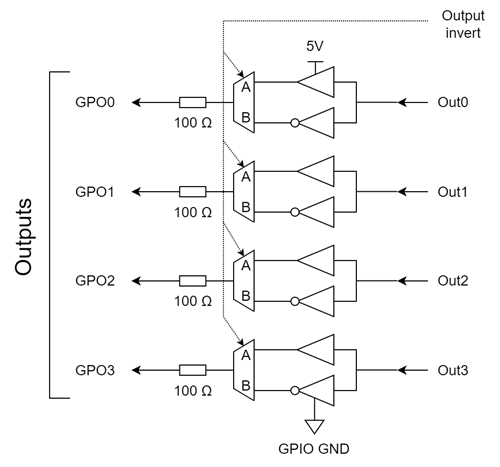
Electrical Characteristics of the Physical Outputs#
| Description | Minimum | Typical | Maximum | Unit |
|---|---|---|---|---|
| Output voltage high (VOH) | 3.8 | 5 | VDC | |
| Output voltage low (VOL) | 0.58 | VDC | ||
| Output current (IO) | 18 | mA |
5V Out (max. current 500 mA): The Front GPIO offers a voltage out pin that provides 5 VDC. It can be used for a current of maximal 500 mA.
Timing Characteristics of the Physical Outputs#
| Timing | Minimum | Typical | Maximum | Unit |
|---|---|---|---|---|
| Rise Time Fall Time | 2.5 | ns |
Info
For details on the electrical and timing characteristics of the Front GPIO outputs, refer to the TI SN74LVC1G97 data sheet.
For details on the RS 485 transceiver, refer to the TI SN65HVD1176 data sheet.
GPIO 34-Pin Flat Cable Connector#
Via the 34-pin flat cable connector (GPIO), you can connect the frame grabber to a trigger extension board.
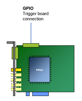
The following figure shows how the frame grabber may be used in conjunction with a trigger extension board:
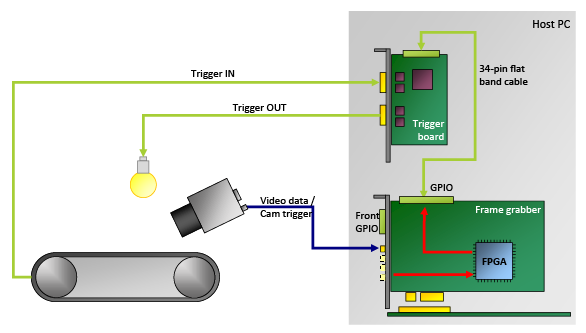
The GPIO connector offers
- 8 digital inputs (IN 0–7)
- 8 digital outputs (OUT 0–7).
The eight inputs are numbered from 0 to 7. The eight outputs range from 0 to 7.
The GPIO connector is used for connecting a trigger extension board. How the physical interface of the trigger extension board is configured (TTL or opto-decoupled, pull-up, pull-down, differential, or single-ended signals) depends on the trigger extension board you are using. For details, see Opto-Coupled Trigger 5 or TTL Trigger.
For installation instructions, see Installing a Trigger Extension Board.
For details on connecting one or multiple frame grabber devices to one or multiple trigger boards, see Synchronizing Multiple Boards.
Pin Layout for the GPIO 34-Pin Flat Cable Connector#
The 34-pin flat cable can connect the frame grabber to an external trigger board. All Basler frame grabbers offer 8 digital inputs (IN 0–7) and 8 digital outputs (OUT 0–7).
You can configure how the individual inputs and outputs are used via applet. Refer to the documentation of the applet you're using.
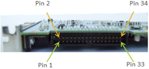
| Pin # (Odd) | I/O Name | Pin # (Even) | I/O Name |
|---|---|---|---|
| 1 | Trigger Output 0 | 2 | +3.3 VDC |
| 3 | Trigger Output 1 | 4 | +3.3 VDC |
| 5 | Trigger Output 2 | 6 | GND |
| 7 | Trigger Output 3 | 8 | GND |
| 9 | Trigger Input 0 | 10 | GND |
| 11 | Trigger Input 1 | 12 | GND |
| 13 | Trigger Input 2 | 14 | GND |
| 15 | Trigger Input 3 | 16 | GND |
| 17 | Trigger Output 4 | 18 | GND |
| 19 | Trigger Output 5 | 20 | GND |
| 21 | Trigger Output 6 | 22 | GND |
| 23 | Trigger Output 7 | 24 | GND |
| 25 | Trigger Input 4 | 26 | GND |
| 27 | Trigger Input 5 | 28 | GND |
| 29 | Trigger Input 6 | 30 | GND |
| 31 | Trigger Input 7 | 32 | VCCIO (+2.5 VDC/ 3.3 VDC) |
| 33 | Presence Detect | 34 | VCCIO (+2.5 VDC/ 3.3 VDC) |
Per default, signals are driven by open-collector drivers, but can be switched to push-pull by software. Pull-ups are on-board.
Refer to the sections Opto Trigger 5 and TTL Trigger to learn how trigger extension boards are connected and used. Refer to the specific applet documentation to learn how the trigger signals can be used.
Notice
The frame grabber trigger system needs to get supply voltage on the Voltage IN pins. If you want to connect devices that have no PWR pin, you must provide the power supply to the Voltage IN pin from an external source.
Trigger Extension Boards#
Trigger extension boards are useful to perform various tasks at small latencies, for example:
- Controlling cameras
- Controlling peripheral devices
- Synchronizing multiple frame grabbers
All trigger extension boards available for Basler frame grabbers offer the following:
- 8 digital inputs (IN 0–7) (8 single-ended signals or 4 differential signals)
- 8 digital outputs (OUT 0–7).
For more information, see Opto-Coupled Trigger 5 and TTL Trigger.
Applet-Specific Trigger Settings#
Using applets, you can configure how the individual I/Os of the trigger extension board are employed. Refer to Configuring the Trigger Options within an Applet and to the documentation of the specific applet you're using.
Configuring the Trigger Options within an Applet#
You can access the trigger configuration of an applet as follows:
- microDisplay X: Allows you to trigger parameter values via GUI.
- Framegrabber API: Allows the frame grabber to be integrated into a specific image processing application.
The demands on the trigger system vary depending on your application:
- For area scan, only one trigger type is required (frame trigger).
- For line scan, two trigger types are required: Line trigger (sends a trigger pulse for each line) and frame trigger. In a line scan application, the frame trigger controls how many lines are appended to an image.
For information which parameters are available (and which effects settings may have), refer to the documentation of the applet you are using.