TTL Trigger#
It adjusts trigger signals to the TTL signal level.
The board offers 8 input and 8 output signals for controlling cameras and peripheral devices. Also, it allows you to synchronize multiple frame grabbers.
Info
The TTL Trigger board is a hardware extension that must be purchased separately. For availability and pricing, see the product page on the Basler website.
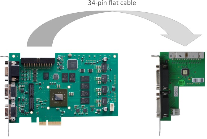
The board can be connected to a frame grabber via a 34-pin flat cable:
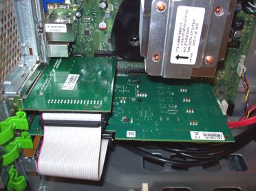
The following image shows the board installed in a computer:
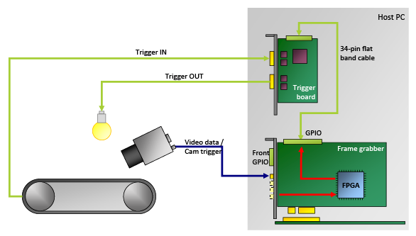
The following image shows an example of a production line using the TTL Trigger board:
Info
You can configure the individual I/Os of the trigger extension board using applets. Refer to the documentation of your specific applet.
Package Contents#
The following items are included in the package:
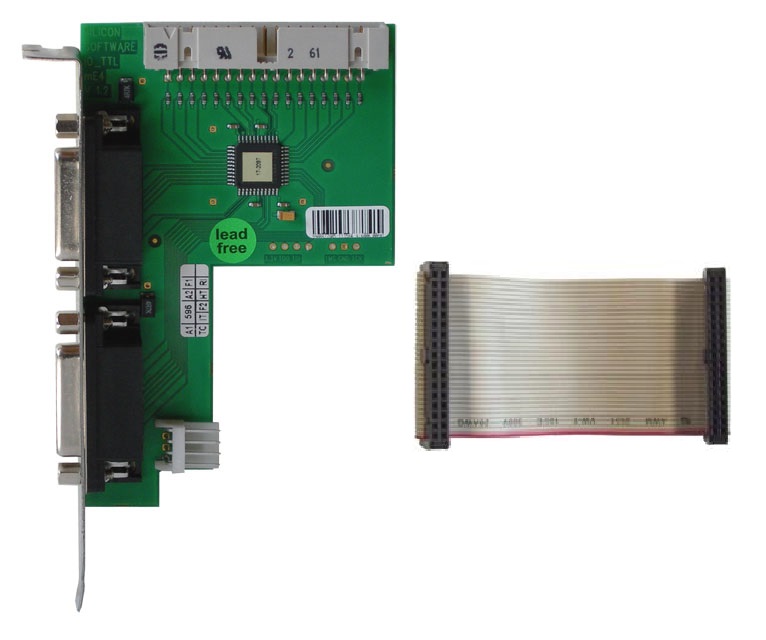
- TTL Trigger (order number 2200000373)
- 34-pin flat cable for connecting the trigger board to the frame grabber
Info
- You can order additional equipment, such as a 34-pin flat cables for multi-board installation, directly from Basler.
- To connect to multiple trigger boards, Basler recommends using a specific 34-pin flat cable provided by Basler, the "Multi-Board Trigger Cable". It offers a connector for the trigger board and multiple connectors for TTL Trigger devices. The signals of the cable use open collector drivers.
The Multi-Board Trigger Cable is available in two variants:- Multi-Board Trigger Cable – Left (order number 2200000374)
- Multi-Board Trigger Cable – Right (order number 2200000480)
Contact Basler Sales for additional ordering information.
Ports#
The following ports are available on the board:
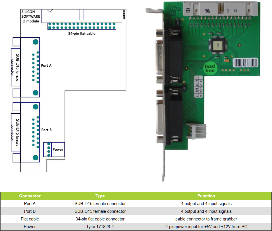
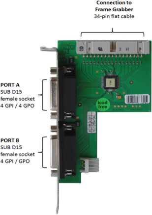
Electrical Environment and Electrical Characteristics#
Electrical Environment#
Internally, the TTL Trigger board operates with LVCMOS33 or LVCMOS25 levels, depending on the attached frame grabber model. All input and output drivers are +5 VDC TTL tolerant.
Electrical Characteristics#
| Min | Max | Unit | |
|---|---|---|---|
| Circuit Speed t PD | 10 | ns | |
| VDC Input Level Low | -0.3 | 0.8 | VDC |
| VDC Input Level High | 2 | 5.5 | VDC |
| VDC Output Level Low | 0.4 | VDC | |
| VDC Output Level High | 2.9 | VDC | |
| I Output Level Low | 8 | mA | |
| I Output Level High | -4 | mA | |
| Temperature Range | -40 | 105 | °C |
Input and Output Signals#
Input Signals#
The TTL Trigger board supports eight input signals (four signals per port). These signals are assigned to the trigger inputs of the frame grabber. They are intended to trigger image or line acquisition. For a functional description of the trigger system, refer to the applet documentation of the frame grabber you are using. The polarity of the input signals is not inverted.
Output Signals#
The TTL Trigger board supports eight output signals (four signals per port). These signals are assigned to the trigger outputs of the of the frame grabber. For a functional description of the trigger system, refer to the applet documentation of the frame grabber you are using.
The polarity of the output signals is not inverted.
Power Supply for Cameras#
Cameras with a +5 VDC or +12 VDC power supply can be powered by the TTL Trigger board. The power supply is available on both front connectors of the TTL Trigger board (SUB-D15).
To provide external power, you must plug a power cable from the computer's power supply to the 4-pin Tyco 171826-4 power connector.
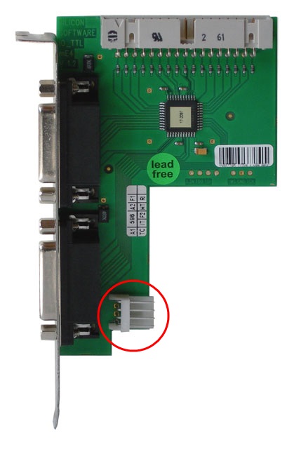
Info
If you want to supply the camera with power via the TTL Trigger board, you must use a 4-pin power supply cable (color code yellow-black-black-red). Connect the 4-pin power connector to the trigger extension board.
Connection to the Frame Grabber#
The frame grabber is connected to the TTL Trigger board via a 34-pin flat cable. The signals of the flat cable use open collector drivers.
This allows you to do the following:
- Use multiple TTL Trigger boards (and Opto-Coupled Trigger 5 boards) at the same time.
- Use a TTL Trigger board with multiple frame grabbers.
Info
- Don't connect frame grabbers across multiple computers.
- To connect to multiple frame grabbers, a custom-made single flat cable with a connector for the TTL Trigger board and multiple connectors for the frame grabbers must be used. Contact your distributor for ordering information.
Pin Layout on SUB-D15#
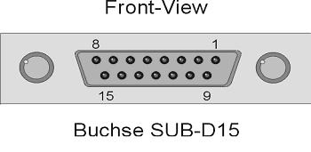
There are two SUB-D15 female plugs on the TTL Trigger board. The upper one is called Port A, the lower one Port B. The following table shows the pin layout SUB-D15 female (Port A and B) on TTL trigger extension board
| Pin Number | SUB-D15 Port A Signal Name | SUB-D15 Port B Signal Name |
|---|---|---|
| 1 | Trigger Output 0 Port A Flash Signal | Trigger Output 4 Port B Flash Signal |
| 2 | Trigger Output 1 Port A For Area Cameras: Image Trigger (Ex Sync) For Line Cameras: Line Trigger (Ex Sync 2) | Trigger Output 5 Port B For Area Cameras: Image Trigger (Ex Sync) For Line Cameras: Line Trigger (Ex Sync 2) |
| 3 | Trigger Output 2 Port A For Area Cameras: HD Sync For Line Cameras: Line Trigger (Ex Sync) | Trigger Output 6 Port B For Area Cameras: HD Sync For Line Cameras: Line Trigger (Ex Sync) |
| 4 | Trigger Output 3 Port A User Output (DigitalOut Bit#0) | Trigger Output 7 Port B User Output (DigitalOut Bit#0) |
| 5 | nc | nc |
| 6 | GND | GND |
| 7 | nc | nc |
| 8 | + 12 VDC (for external devices only) | + 12 VDC (for external devices only) |
| 9 | + 5 VDC (for external devices only) | + 5 VDC (for external devices only) |
| 10 | nc | nc |
| 11 | Trigger Input 0 Port A | Trigger Input 4 Port B |
| 12 | Trigger Input 1 Port A | Trigger Input 5 Port B |
| 13 | Trigger Input 2 Port A | Trigger Input 6 Port B |
| 14 | Trigger Input 3 Port A | Trigger Input 7 Port B |
| 15 | GND | GND |
Pin Layout Trigger/IO Interface (34-Pin Flat Cable Connector)#
The 34-pin flat cable links the frame grabber and the trigger board. All Basler frame grabbers offer 8 digital inputs (IN 0 – 7) , and 8 digital outputs (OUT 0–7).

The mapping of the connector pins to the individual inputs and outputs is the same for all Basler frame grabbers.
How the individual inputs and outputs are used you can configure via applet. Refer to the documentation of the applet you are using.
The pins of the 34-pin flat cable connector are connected to the following inputs and outputs:
| Pin Number | I/O Name |
|---|---|
| 1 | Trigger Output 0 |
| 2 | +3.3 VDC |
| 3 | Trigger Output 1 |
| 4 | +3.3 VDC |
| 5 | Trigger Output 2 |
| 6 | GND |
| 7 | Trigger Output 3 |
| 8 | GND |
| 9 | Trigger Input 0 |
| 10 | GND |
| 11 | Trigger Input 1 |
| 12 | GND |
| 13 | Trigger Input 2 |
| 14 | GND |
| 15 | Trigger Input 3 |
| 16 | GND |
| 17 | Trigger Ouput 4 |
| 18 | GND |
| 19 | Trigger Ouput 5 |
| 20 | GND |
| 21 | Trigger Ouput 6 |
| 22 | GND |
| 23 | Trigger Ouput 7 |
| 24 | GND |
| 25 | Trigger Input 4 |
| 26 | GND |
| 27 | Trigger Input 5 |
| 28 | GND |
| 29 | Trigger Input 6 |
| 30 | GND |
| 31 | Trigger Input 7 |
| 32 | VCCIO (+ 2.5 VDC) |
| 33 | Presence Detect |
| 34 | VCCIO (+ 2.5 VDC) |
You can configure the parameter settings for each individual input and output in microDisplay X and via Framegrabber API.
Default I/O configuration: 2.5 VDC logic level signals (LVCMOS25). Signals are driven by open-collector drivers, pullups are on-board.