imaFlex CXP-12 Penta#
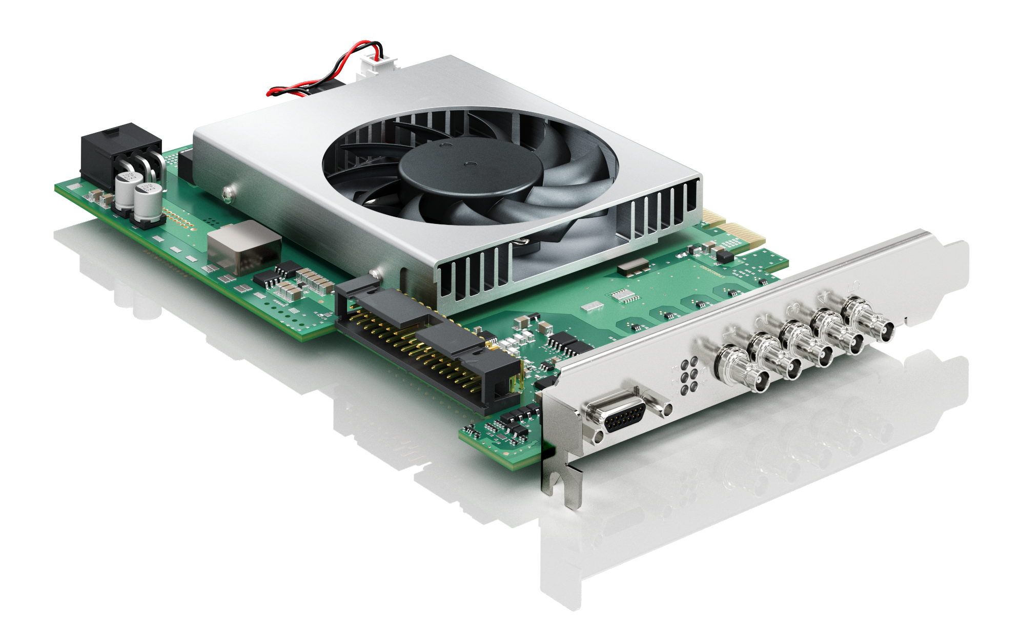
To install the imaFlex CXP-12 Penta in your host computer, plug it into a PCIe Gen. 3.0 x8 slot or higher. The following image shows an imaFlex CXP-12 Penta with five cameras connected to it:
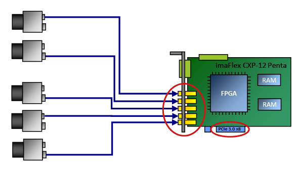
Image Processing#
The frame grabber is fully programmable by VisualApplets. You can design your own image processing application tuned to your specific needs. Basler offers consultancy support, VisualApplets trainings and of course Basler can also implement for you your specific application.
For information on how to write your own applets with VisualApplets.
Production Line Integration#
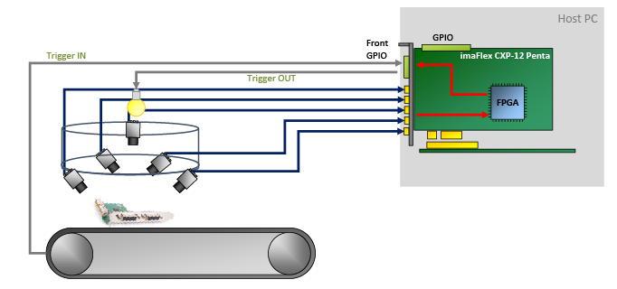
For integration into a production line, imaFlex CXP-12 Penta offers multiple general purpose inputs and outputs. 8 (with the TTL Trigger board) or 24 (with the Opto-Coupled Trigger 5 board) of the GPIOs (depending on the hardware add-ons used) are galvanically isolated.
These GPIOs enable you to do the following:
- Control peripheral devices by sending trigger signals, e.g. lighting signals and cameras signals
- Receive various trigger signals from peripheral devices, e.g., shaft encoders and light barriers
- Synchronize multiple imaFlex CXP-12 Penta frame grabbers, and/or
- Synchronize connected devices.
Software Programming and Configuration Interface#
imaFlex CXP-12 Penta offers an easy-to-use API. The Framegrabber API allows to integrate the frame grabber into any image processing application. You can use the Framegrabber API to write code in the following languages:
- C/C++
- C# (wrapper available)
- Python (wrapper available)
For more information about the Framegrabber API, see the Framegrabber API documentation.
Alternatively, you can use Basler's GenTL Interface to develop your application in form of a GenTL consumer. For more information about the Basler GenTL Interface, see GenTL Interface documentation.
Connectors and LEDs#
Connectors#
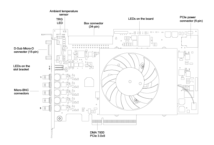
imaFlex CXP-12 Penta has the following connectors:
LEDs on the Slot Bracket#
There are five LEDs located on the slot bracket of imaFlex CXP-12 Penta that indicate the state of the individual CXP links:
![]() Connection at CXP link ready for operation
Connection at CXP link ready for operation
![]() No connection at CXP link
No connection at CXP link
LEDs on the Board#
| LED Name | LED Color | Meaning |
|---|---|---|
| TRG | Yellow | External voltage supplied via the 15-pin connector. |
| READY | Orange | The FPGA has been configured successfully and is ready for operation. |
| PG_INT | Green | PG_INT=Power Good Internal Voltage on the PCIe slot is stable. The voltage generated internally is also stable. |
| PGEXT | Green | Not defined/internal function. |
| USR1 to USR6 | Green | User-defined. The LEDs can be controlled via VisualApplets software. They are not related to camera connectors and can be used for any purpose. |
| 12V | Green or red | Off: The framegrabber is not powered. Red: The frame grabber receives power only via the PCIe slot (12 VDC IN). Green: The frame grabber's 6-pin (12V) power connector is connected to a power supply via the host computer. |
Specifications#
| imaFlex CXP-12 Penta | |
|---|---|
| Host Interface | PCIe Gen 3 x8 (Direct Memory Access) |
| Bandwidth (typ./max.) | 6520 MB/s |
| On-Board Memory | 2.5 GB DDR4-RAM |
| Power Supply (Input) / Current PCIe Slot | 12 V (±5 %) / <1.5 A (actual values depend on processing) |
| Power Supply (Input) / Current PCIe 6-pin Connector | 12 V (±5 %) / <6.5 A (actual values depend on connected PoCXP cameras) |
| PoCXP Supply (Output) | 17 W of 24 V DC regulated power per CoaXPress connector |
| Size (L x H) | PCIe standard height Half length card: 167.64 mm x 111.15 mm |
| Weight | 270 g |
| Camera Interface | 5 x CXP-12 (CXP-1 to CXP-12, micro-BNC/HD-BNC connector) |
| Ambient Temperature | 50 °C An adequate airflow in the computer is recommended. |
| Operating Temperature | 0–50 °C at 100 LFMa |
| Storage Temperature | -50–80 °C |
| Humidity during Operation | 5–90 % |
| Humidity during Storage | 5–95 % |
| Compliance | CE, FCC, RoHS, WEEE, REACH, UKCA, UL Recognized, KC Certificates for your interface card For more information, see the Compliance section of the Basler website. |
-
LFM = Linear Feet per Minute, unit for measuring airflow velocity. ↩
Info
The PCIe bus data throughput depends on the mainboard, the chip set, and the BIOS configuration of the host computer. The number of installed PCIe boards also affects the throughput, e.g. a PCIe x8 connector may support only x4 performance. Always check the mainboard manual thoroughly to be sure.
The Front GPIO Connector#
The front GPIO connector covers the basic trigger setup of your frame grabber. Its trigger connector allows you to control peripheral devices (PLC).
The socket is located directly on the slot bracket:
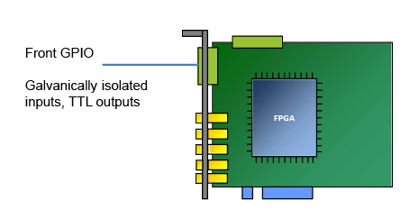
In default configuration, the trigger connector of the front GPIO connector offers:
- 3 differential input signals or 2 differential and 1 single-ended input signal in pull-up mode
- 4 TTL output signals
Info
You can configure the pin assignment of the front GPIO connector to provide different input signals, e.g.:
- Pull-down
- 4 single-ended signals (and no differential signals).
To change the GPIO configuration, use the command line tool installed with the Framegrabber SDK.
For more information, see Input Configuration and Configuring the Physical Properties of Trigger Signals with the gpioTool.
Pin Layout of the Front GPIO Connector#

Info
The front GPIO connector is provided in form of a MOLEX 83612-9020 connector. For this connector, a matching, ready-made MOLEX D-Sub cable is available (MOLEX 083422-9018).
| PIN Number (3P FPGA) | Galvanically Isolated | Signal | Reference Signal |
|---|---|---|---|
| 1 | Yes | GPO 0 (TTL) | 5 V / GPIO GND (pin 6 and 15) |
| 2 | Yes | GPO 1 (TTL) | 5 V / GPIO GND (pin 6 and 15) |
| 3 | Yes | GPO 2 (TTL) | 5 V / GPIO GND (pin 6 and 15) |
| 4 | Yes | GPO 3 (TTL) | 5 V / GPIO GND (pin 6 and 15) |
| 5 | No | 5 V_OUT (isolated 5V output, max 500mA) | GPIO GND (pin 6 and 15) |
| 6 | No | GPIO GND (Isolated GND) | |
| 7 | No | — (not connected) | |
| 8 | Yes | GPI 2 (GPI2+ if used for differential signal) | GPI voltage IN (pin 10) / GPIO GND (pin 6 and 15) |
| 9 | Yes | GPI 3 (GPI2- if used for differential signal) | GPI voltage IN (pin 10) / GPIO GND (pin 6 and 15) |
| 10 | Yes | GPI voltage IN (4.5–28 V input for pullups / comparators. VIN_REF is 20% of VIN) | GPIO GND (pin 6 and 15) |
| 11 | Yes | GPI 0+ | GPI voltage IN (pin 10) / GPIO GND (pin 6 and 15) |
| 12 | Yes | GPI 0- | GPI voltage IN (pin 10) / GPIO GND (pin 6 and 15) |
| 13 | Yes | GPI 1+ | GPI voltage IN (pin 10) / GPIO GND (pin 6 and 15) |
| 14 | Yes | GPI 1- | GPI voltage IN (pin 10) / GPIO GND (pin 6 and 15) |
| 15 | Yes | GPIO GND (isolated GND) | |
| Shield | No | GND (Non-isolated ground / Earth / bracket) |
Possible Topologies#
There are many possibilities to connect cameras with 1, 2, or 4 CXP channels to imaFlex CXP-12 Penta. The maximal amount of used CXP channels in total over all cameras is 5 CXP-12 channels. Each camera can operate at different CXP bitrates. All CXP 2.0 bitrates are supported for each CXP camera independently.
You can operate imaFlex CXP-12 Penta as follows:
| Topology | Number of Cameras | Number of Channels | Topology |
|---|---|---|---|
| One camera one channel single | 1 | 1 | 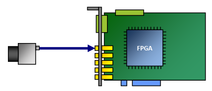 |
| One camera two channels single | 1 | 2 | 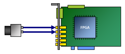 |
| One camera four channels single | 1 | 4 | 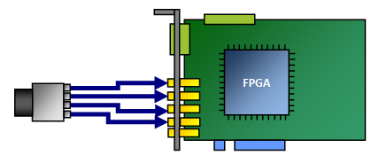 |
| Two cameras one channel each penta | 2 | 2 | 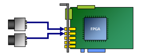 |
| Three cameras one channel each penta | 3 | 3 | 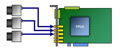 |
| Four cameras one channel each penta | 4 | 4 | 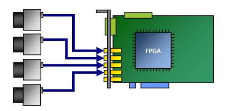 |
| Five cameras one channel each penta | 5 | 1 | 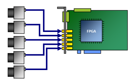 |
When connected to the computer power supply via the PCIe 6-pin connector, which always provides 12 V, imaFlex CXP-12 Penta supports Power over CXP (PoCXP).
You may connect the cameras in any order. The connection topology is totally independent on the port number. Any camera channel can be connected to any frame grabber CXP port. The CXP 2.0 topology discovery will reorder the channels virtually in software according to the cameras and VisualApplets applet configuration.
Info
If you are going to use multiple imaFlex CXP-12 Penta boards in one host computer, make sure you have one PCIe Gen. 3.0 x8 slot or higher per board available in the host computer. For more information, see the following topics:
Acquisition Applets#
To ensure optimum use of system resources, not all image acquisition and processing features designed for imaFlex CXP-12 Penta are loaded onto imaFlex CXP-12 Penta simultaneously.
Instead, Basler provides various compilations of specific image acquisition and processing features that are combined to meet the requirements of a specific application field.
Typically, an applet supports a specific camera interface standard and topology, specific image acquisition features, and possibly specific image (pre-)processing features.
There are two kinds of applets: acquisition applets (*.dll) always delivered by Basler, and custom applets (*.hap) developed in VisualApplets either by yourself or by Basler. imaFlex CXP-12 Penta is delivered with one Test Applet. All other applets need to be designed with VisualApplets.
Refer to Acquisition Applets for imaFlex CXP-12 Penta for more information about the Test Applet.