marathon ACX-SP#
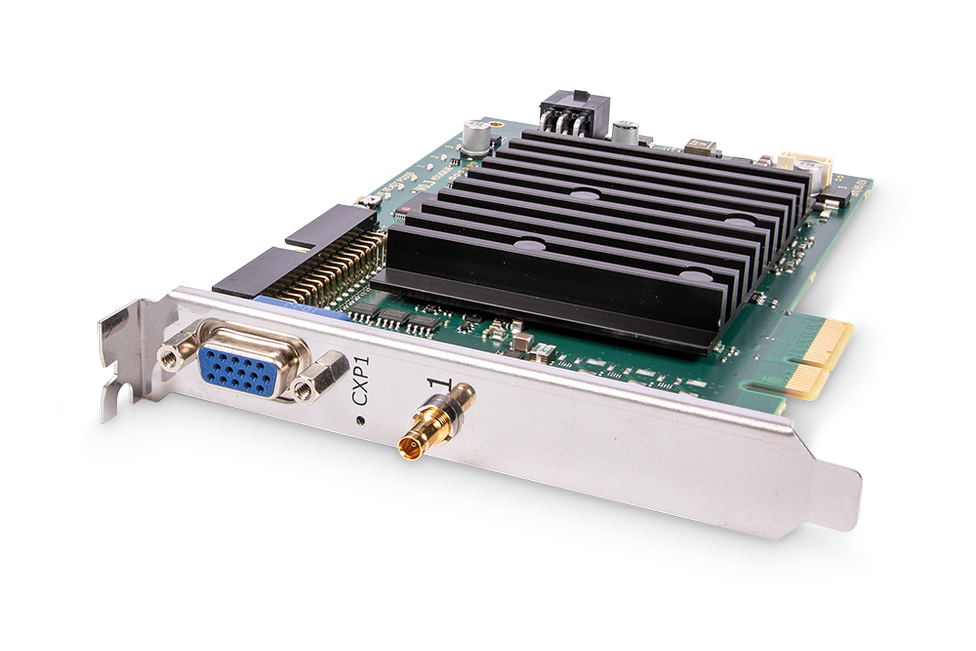
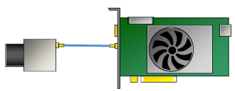
要在计算机中安装 marathon ACX-SP,请将其插入 PCIe Gen. 2 x4 或更高规格的插槽中。下图显示了连接了一台相机的 marathon ACX-SP:
图像处理#
图像处理功能可根据需求提供。如有兴趣,请联系 Basler 支持。
生产线集成#
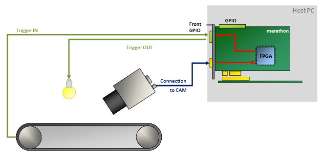
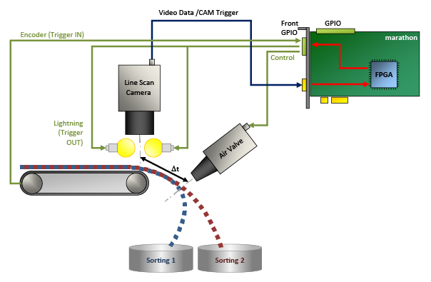
为了集成到生产线中,marathon ACX-SP 提供了多个通用输入和输出。其中 4 到 20 个 GPIO(取决于所使用的硬件附件)采用电隔离。
这些 GPIO 使您能够执行以下操作:
- 通过发送触发信号(例如照明信号和相机信号)来控制外围设备。
- 接收来自外围设备(例如轴编码器和光电开关)的各种触发信号。
- 同步多个 marathon ACX-SP 采集卡。
- 同步连接的设备。
软件编程和配置接口#
marathon ACX-SP 提供易于使用的 API。通过 Framegrabber API,您可以将采集卡集成到任意图像处理应用程序中。您可以使用 Framegrabber API 编写使用以下语言的代码:
- C/C++
- C#(提供封装)
- Python(提供封装)
有关 Framegrabber API 的更多信息,请参见 Framegrabber API 文档。
或者,您可以使用 Basler GenTL 接口开发 GenTL 消费者形式的应用。有关 Basler GenTL 接口的更多信息,请参见 GenTL 接口文档。
连接器和 LED#
连接器#
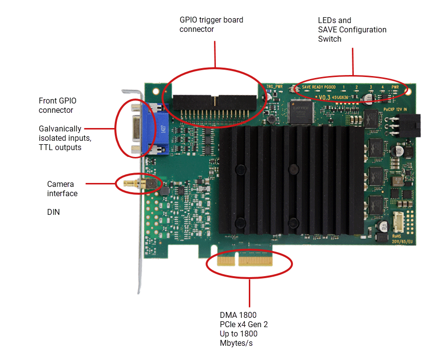
marathon ACX-SP 具有以下连接器:
配置开关#
除端口外,marathon ACX-SP 还提供一个板载配置开关,用于激活称为 SAVE configuration 的回退 FPGA 配置。有关 SAVE configuration 的详细信息,请参见 FPGA Fall-Back Configuration。
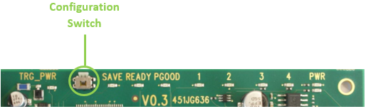
插槽托架上的 LED 指示灯#
marathon ACX-SP 的挡板上有一个 LED,用于指示 CXP 链路的状态:
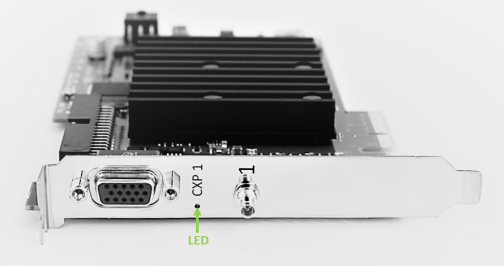
 CXP 链路连接已准备就绪,可投入运行
 CXP 链路无连接
板上的 LED 指示灯#

| LED 名称 | LED 颜色 | 含义 |
|---|---|---|
| TRG_PWR | 绿色 | 前置 GPIO 已连接至外部电源(电源输入)。 |
| SAVE | RED | SAVE configuration 用于 FPGA 配置 |
| READY | 橙色 | FPGA 已成功配置并准备就绪,可以运行。当 FPGA 使用 SAVE 配置时,LED READY 也会亮起。 |
| PGOOD | 橙色 | PGOOD = Power Good 所有电压均已正确施加。 |
| 1 | 橙色 | 用户定义。这些 LED 可通过软件进行控制。它们与相机连接器无关,可用于任何目的。 |
| 2 | 橙色 | 用户定义。这些 LED 可通过软件进行控制。它们与相机连接器无关,可用于任何目的。 |
| 3 | 橙色 | 用户定义。这些 LED 可通过软件进行控制。它们与相机连接器无关,可用于任何目的。 |
| 4 | 橙色 | 用户定义。这些 LED 可通过软件进行控制。它们与相机连接器无关,可用于任何目的。 |
| PWR(上方 LED) | 绿色 | 采集卡通过 PCIe 接口接收 12 VDC 输入。 |
| PWR(下方 LED) | 绿色 | 采集卡通过计算机电源连接器获取电压 IN,以便通过 CXP 电缆为相机供电。 |
规格#
| marathon ACX-SP | |
|---|---|
| 订单号 | 2200000356 |
| 主机接口 | PCIe Gen 2 x4(直接内存访问) |
| 带宽(典型值/最大值) | 最高 1.8 GB/s 的持续数据带宽 |
| 板载 Memory | 512 MB DDR3-RAM |
| 电源(输入)/ 电流 PCIe 插槽 | 12 VDC (±5 %) / <1.5 A (actual values depend on processing) |
| 电源(输入)/电流 PCIe 6 引脚连接器 | 12 VDC (±5 %) / <6.5 A (actual values depend on connected PoCXP cameras) |
| PoCXP 供电(输出) | 每个 CoaXPress 连接器提供 17 W 的 24 VDC 稳压电源 |
| 功耗 | 典型值 0.8 A @ 12 VDC(实际值取决于图像预处理) |
| 尺寸(长 x 高) | PCIe 标准高度 半高卡: 167.64 mm x 111.15 mm |
| 重量 | 200 g |
| 相机接口 | 1 x CXP-6(CXP-1 至 CXP-6,DIN 连接器) |
| 环境温度 | 50 °C (0 LFMa) 60 °C (100 LFMa) 建议计算机内保持充足的气流。 |
| FPGA 工作温度b | 0–85 °C @ 100 LFMa |
| 存放温度 | -50-80°C |
| 工作期间的湿度 | 5–90 % 非冷凝 |
| 存储期间的湿度 | 5%-95% |
| 合规性 | CE、RoHS、UKCA |
信息
PCIe 总线数据吞吐量取决于主板、芯片组以及主机的 BIOS 配置。安装的 PCIe 板卡数量也会影响吞吐量,例如 PCIe x8 连接器可能仅支持 x4 性能。请务必仔细检查主板手册以确保符合要求。
前面板 GPIO 连接器#
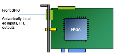
前置 GPIO 连接器涵盖了采集卡的基本触发设置。其触发连接器允许您控制外围设备 (PLC) 并同步多个 marathon ACX-SP 板。
该插座位于插槽挡板上:
在默认配置下,前面板 GPIO 连接器的触发连接器提供以下功能:
- 上拉模式下的 3 个差分输入信号,或 2 个差分和 1 个单端输入信号
- 2 个 TTL 输出信号
信息
您可以配置前面板 GPIO 连接器的引脚分配以提供不同的输入信号,例如:
- 下拉
- 4 个单端信号(无差分信号)。
若要更改 GPIO 配置,请使用随 Framegrabber SDK 一起安装的命令行工具。
前面板 GPIO 连接器引脚排布#
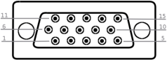
| 引脚编号 (3P FPGA) | 电气隔离 | 信号 | 参考信号 |
|---|---|---|---|
| 1 | 无 | GPO 0 (TTL) | 5 VDC / 全局 GND(引脚 6) |
| 2 | 无 | GPO 1 (TTL) | 5 VDC / 全局 GND(引脚 6) |
| 3 | 无 | 预留用于 RS 485 (GND) | |
| 4 | 无 | 预留用于 RS 485 | |
| 5 | 无 | — | |
| 6 | 无 | GND(全局接地) | |
| 7 | 无 | 5 V_OUT(最大 0.5 A) | |
| 8 | 是 | GPI 2(如果用于差分信号则为 GPI2+) | GPI 电压输入(引脚 10)/ GPI GND(引脚 15) |
| 9 | 是 | GPI 3(如果用于差分信号则为 GPI2-) | GPI 电压输入(引脚 10)/ GPI GND(引脚 15) |
| 10 | 是 | GPI 电压输入 (4.5–28 VDC) | |
| 11 | 是 | GPI 0+ | GPI 电压输入(引脚 10)/ GPI GND(引脚 15) |
| 12 | 是 | GPI 0- | GPI 电压输入(引脚 10)/ GPI GND(引脚 15) |
| 13 | 是 | GPI 1+ | GPI 电压输入(引脚 10)/ GPI GND(引脚 15) |
| 14 | 是 | GPI 1- | GPI 电压输入(引脚 10)/ GPI GND(引脚 15) |
| 15 | 是 | GPI 接地 |
用于电隔离电路的额外电压输入/GND#
前面板 GPIO 连接器的所有通用输入(GPI)均经过电隔离。传入的信号通过数字隔离器传输至采集卡。通过这种方式,采集卡可以得到安全保护,免受高输入电压的影响。
然而,若要运行内部 GPI 电路,您必须连接电压源和接地:在引脚 10 上施用作为内部运算放大器工作电压的电压(GPI 伏特 IN);在引脚 15 上连接相应的接地(GPI GND)。
所需供电电压
marathon ACX-SP 触发系统需要向 GPI Voltage IN 引脚(引脚 10)提供供电电压。如果要连接没有 PWR 引脚的设备,则必须从外部电源为 GPI Voltage IN 引脚(引脚 10)供电。
可能的拓扑#
您可以通过一台相机操作 marathon ACX-SP:相机可通过一根 CXP 线路连接到 marathon ACX-SP,最高速度为 6.25 Gbit/s (CXP6):
| 相机数量 | 相机端口数 | 采集卡端口数 | 模式 | 拓扑 |
|---|---|---|---|---|
| 1 | 1 | 1 | Bayer 格式 | 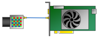 |
| 1 | 1 | 1 | 灰度 | 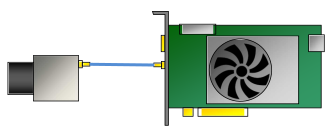 |
| 1 | 1 | 1 | RGB | 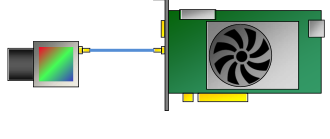 |
当通过始终提供 12 V 电压的 PCIe 6 引脚连接器连接到计算机电源时,marathon ACX-SP 支持 Power over CXP (PoCXP)。
信息
如果您打算在一台主计算机中使用多个 imaFlex CXP-12 Quad 板卡,请确保主计算机中每块板卡都有一个 PCIe Gen. 3.0 x8 或更高规格的插槽可用。有关更多信息,请参见 Using Multiple Boards in one Host。
要了解哪种拓扑结构适用于哪种 Applet,请参阅选择合适的面阵扫描 Applet 或选择合适的线阵扫描 Applet。
采集小程序#
为确保优化使用系统资源,并非专为 marathon ACX-SP 设计的所有图像采集和处理功能都会同时加载到 marathon ACX-SP 上。
相反,Basler 提供了各种特定图像采集和处理功能的组合,这些功能相结合以满足特定应用领域的要求。
通常,一个 applet 支持特定的相机接口标准和拓扑、特定的图像采集功能,以及可能特定的图像(预)处理功能。
Applets 以 .dll 文件形式提供。
有关随附的 Acquisition Applets 及其对所用拓扑的依赖性的更详细信息,请参考 Acquisition Applets for marathon ACX-SP。
有关随附的 Acquisition Applets(GenTL 和 Fglib)的 PDF 文档,请参见 Acquisition Applets for marathon ACX-SP Documentation。
预防措施#
→ 请参阅安全说明(图像采集卡)。
安装#
→ 请参阅连接图像采集卡。
→ 请参阅连接相机。