Installing a Trigger Extension Board#
Prerequisites#
You can only install one of the following trigger extension boards:
Both boards must be purchased separately.
Info for Opto-Coupled Trigger 5
Before installation, check whether you'll be able to access the DIP switches on the board after the board has been installed. If not, Basler recommends setting the DIP switches before installing the board into the host computer.
For more information about the DIP switches, see Configuring the Physical Interface.
Info
Make sure there's an adequate ventilation system within your computer, especially in the following cases:
- There is little space between boards in a multi-board installation.
- A board is installed close to a graphics card.
Basler recommends leaving enough free space between boards.
You need the following components:
- microEnable frame grabber
- Trigger extension board
- 34-pin flat cable
Installing the Board#
To install the trigger extension board:
- Shut down the host computer.
- Disconnect the host computer from power.
-
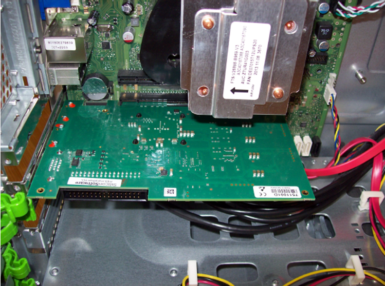
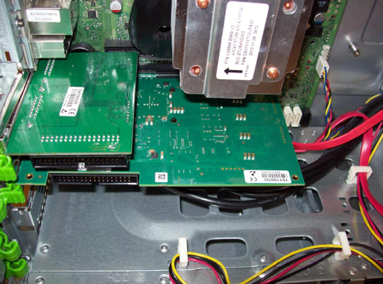
Insert the trigger board into an empty slot on the slot bracket of the host computer.


-
Attach the trigger board to the computer case with screws.
-
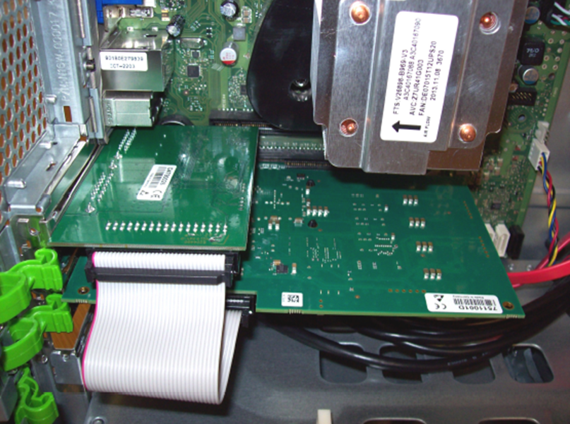
Connect the trigger board with the GPIO socket of your microEnable frame grabber using the 34-pin flat cable.

-
Reboot your computer.
Now, the trigger board is ready for use.
Info
For information about using multiple microEnable frame grabbers with one trigger board or vice versa, see Using Multiple Boards.