跳转到内容

marathon ACL#

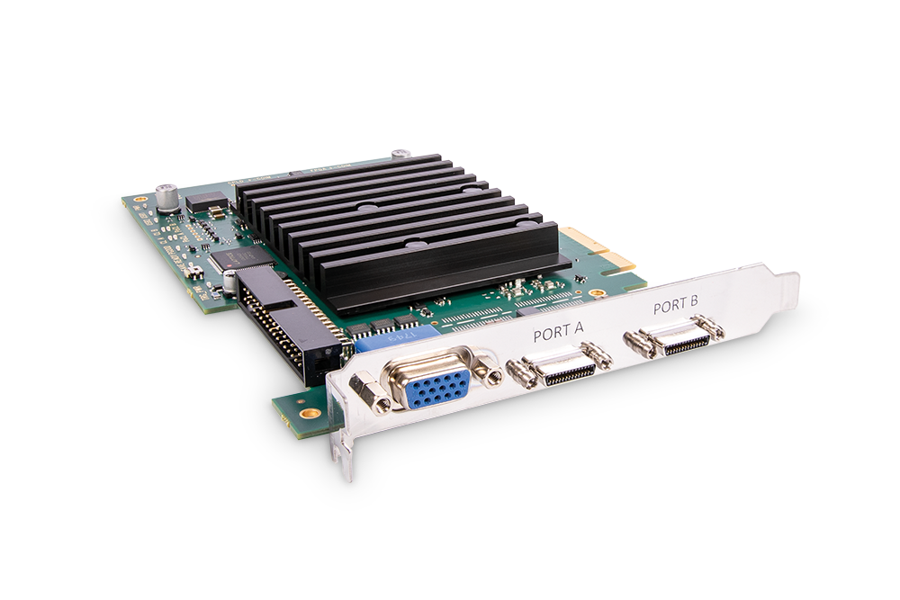
marathon ACL is a Camera Link frame grabber. When connected to the computer power supply, marathon ACL supports Power over Camera Link (PoCL SafePower 4W/12V per port).

Depending on the applets you are running on the board, you may need to enable the PoCL support via microDiagnostics. The automatic PoCL detection is disabled per default on marathon ACL when running standard applets version 2.0 or higher, or when running individual applets created with VisualApplets version 3.0.6 or higher. When you use PoCL cameras together with such applets, you must enable automatic PoCL detection. This is possible in microDiagnostics (runtime version 5.5.1 or higher). For details, see Enabling PoCL Support.

marathon ACL

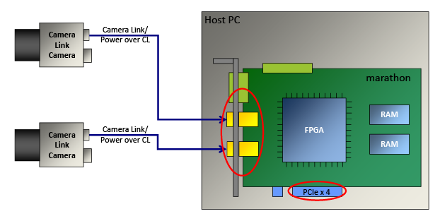
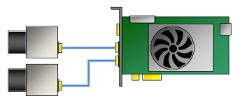
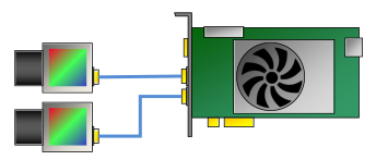
To install the marathon ACL in your computer, plug it into a PCIe Gen. 2 x4 slot or higher. The following image shows a marathon ACL with two Camera Link cameras connected:

PCIe Connection

Image Processing#

Image processing functionality is available on request. If you are interested, contact Basler Support.

Production Line Integration#

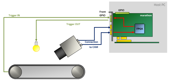
For integration into a production line, marathon ACL offers multiple general purpose inputs and outputs. Depending on the hardware add-ons used, 4 to 20 GPIOs are available, also galvanically isolated.

These GPIOs enable you to do the following:

  • Control peripheral devices by sending trigger signals, e.g. lighting signals and cameras signals.
  • Receive various trigger signals from peripheral devices, e.g., shaft encoders and light barriers.
  • Synchronize multiple marathon ACL frame grabbers
  • Synchronize connected devices.

marathon ACL within the Production Line (Example)

Communication between camera and marathon ACL is realized via serial interface and four CC signals per Camera Link cable.

Software Programming and Configuration Interface#

marathon ACL offers an easy-to-use API. The Framegrabber API allows to integrate the frame grabber into any image processing application. You can use the Framegrabber API to write code in the following languages:

  • C/C++
  • C# (wrapper available)
  • Python (wrapper available)

For more information about the Framegrabber API, see the Framegrabber API documentation.

Alternatively, you can use Basler's GenTL Interface to develop your application in form of a GenTL consumer. For more information about the Basler GenTL Interface, see GenTL Interface documentation.

Connectors and LEDs#

连接器#

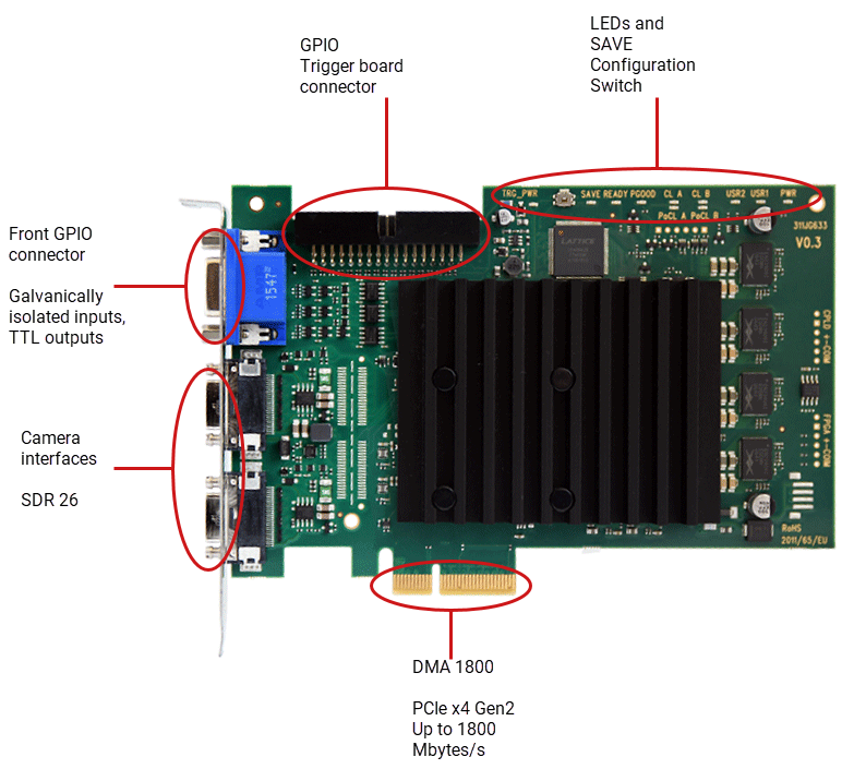
marathon ACL has the following connectors:

marathon ACL with Connectors

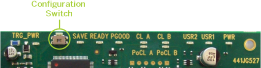
Configuration Switch#

marathon ACL offers an on-board configuration switch for activating a fall-back FPGA configuration, called SAVE configuration. For details regarding the SAVE configuration, see FPGA Fall-Back Configuration.

Configuration Switch

板上的 LED 指示灯#

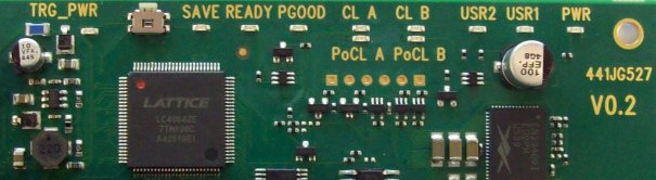
marathon ACL provides the following LEDs on the board:

marathon CXP-SP LEDs on the Board

LED 名称 LED 颜色 含义
TRG_PWR 绿色 Front GPIO is connected to external power (power IN).
SAVE RED SAVE configuration is used for FPGA configuration
READY 橙色 The FPGA has been configured successfully and is ready for operation. LED READY also gives light when SAVE configuration is used on FPGA.
PGOOD 橙色 PGOOD=Power Good
All voltages are applied correctly.
CL A 橙色 Port A is connected to a camera that provides a clock.
CL B 橙色 Port B is connected to a camera that provides a clock.
PoCL A 绿色 Power over Camera Link active on port A: Camera on port A is provided with power by frame grabber via Camera Link cable.
PoCL B 绿色 Power over Camera Link active on port B: Camera on port B is provided with power by frame grabber via Camera Link cable.
USR1 橙色 User-defined. The LEDs can be controlled via software. They aren't related to camera connectors and can be used for any purpose.
USR2 橙色 User-defined. The LEDs can be controlled via software. They aren't related to camera connectors and can be used for any purpose.
PWR 绿色 Frame grabber gets 12 VDC IN via PCIe interface.

规格#

marathon ACL
订单号 2200000358
主机接口 PCIe Gen 2 x4 (Direct Memory Access)
Bandwidth (typ./max.) Up to 1.8 GB/s sustainable data bandwidth (maximal Camera Link data rate 850 MByte/s)
On-Board Memory 512 MByte DDR3-RAM
Power Supply (Input) / Current PCIe Slot 12 VDC (±5 %) / <1.5 A (actual values depend on processing)
PoCXP 供电(输出) 4 W of 12 VDC regulated power per each Camera Link connector
功耗 Typ. 1 A @ 12 VDC (actual values depend on processing)
Size (L x H) PCIe 标准高度
半高卡:
167.64 mm x 111.15 mm
重量 200 g
相机接口 2 x Camera Link 2.0 standard (2 * SDR 26) (mini CL)
Ambient Temperature 50 °C (0 LFMa)
60 °C (100 LFMa)
An adequate airflow in the computer is recommended.
FPGA Operating Temperatureb 0–85 °C at 100 LFMa
存放温度 -50-80°C
工作期间的湿度 5–90 % non-condensing
存储期间的湿度 5%-95%
Compliance CE, FCC, UKCA, RoHS

  1. LFM = Linear Feet per Minute, unit for measuring airflow velocity. 

  2. Temperature being measured directly on the FPGA. You can read out the measured value in all applets that are available for marathon ACL via the applet parameter FG_SYSTEMMONITOR_FPGA_TEMPERATURE

信息

The PCIe bus data throughput depends on the mainboard, the chip set, and the BIOS configuration of the host computer. The number of installed PCIe boards also affects the throughput, e.g. a PCIe x4 connector may support only x1 performance. Always check the mainboard manual thoroughly to be sure.

The Front GPIO Connector#

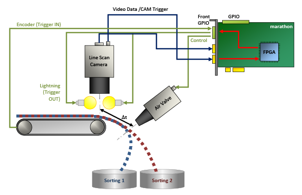
The front GPIO connector covers the basic trigger setup of your frame grabber. Its trigger connector allows you to control peripheral devices (PLC) and to synchronize multiple marathon ACL boards.

marathon ACL Using the Front GPIO Connector for Trigger IN/Trigger OUT (Example: Bulk Sorting)

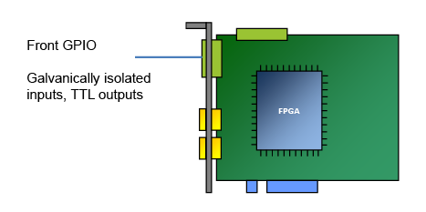
The socket is located directly on the slot bracket:

The Front GPIO Connector

In default configuration, the trigger connector of the front GPIO connector offers:

  • 3 differential input signals or 2 differential and 1 single-ended input signal in pull-up mode
  • 2 TTL output signals

信息

You can configure the pin assignment of the front GPIO connector to provide different input signals, e.g.:

  • Pull-down
  • 4 single-ended signals (and no differential signals).

To change the GPIO configuration, use the command line tool installed with the Framegrabber SDK.

For more information, see Input Configuration and gpioTool.

Pin Layout of the Front GPIO Connector#

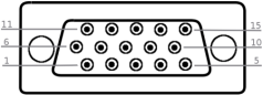
Pins on the Front GPIO Connector

PIN Number (3P FPGA) Galvanically Isolated 信号 参考信号
1 GPO 0 (TTL) 5 VDC / global GND (pin 6)
2 GPO 1 (TTL) 5 VDC / global GND (pin 6)
3 预留用于 RS 485 (GND)
4 预留用于 RS 485
5
6 GND(全局接地)
7 5 V_OUT (0.5 A max)
8 GPI 2 (GPI2+ if used for differential signal) GPI voltage IN (pin 10) / GPI GND (pin 15)
9 GPI 3 (GPI2- if used for differential signal) GPI voltage IN (pin 10) / GPI GND (pin 15)
10 GPI voltage IN (4.5–28 VDC)
11 GPI 0+ GPI voltage IN (pin 10) / GPI GND (pin 15)
12 GPI 0- GPI voltage IN (pin 10) / GPI GND (pin 15)
13 GPI 1+ GPI voltage IN (pin 10) / GPI GND (pin 15)
14 GPI 1- GPI voltage IN (pin 10) / GPI GND (pin 15)
15 GPI 接地
Extra Voltage IN/GND for Galvanically Isolated Circuit#

All General Purpose Inputs (GPIs) of the front GPIO connector are galvanically isolated. The incoming signals are transferred to the frame grabber via digital isolators. This way, the frame grabber is securely protected against high incoming voltages.

However, to operate the internal GPI circuits, you must connect a voltage source and ground: On pin 10, you apply the voltage (GPI voltage IN) that serves as operating voltage for the internal operational amplifiers. On pin 15, you connect the according ground (GPI GND).

Supply Voltage Required

The marathon ACL trigger system needs to get supply voltage on the GPI Voltage IN pin (pin 10). If you want to connect devices that have no PWR pin, you must provide the power supply to the GPI Voltage IN pin (pin 10) from an external source.

可能的拓扑#

You can operate marathon ACL as follows:

相机数量 Number of Camera Ports Number of Frame Grabber Ports Mode 拓扑
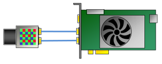
1 1 2 Bayer Pattern One Camera, One Port, Bayer Pattern
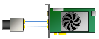
1 1 2 Grayscale One Camera, One Port, Grayscale
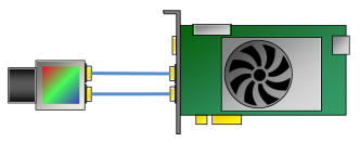
1 1 2 RGB One Camera, One Port, RGB
1 2 2 Bayer Pattern One Camera, Two Ports, Bayer Pattern
1 2 2 Grayscale One Camera, Two Ports, Grayscale
1 2 2 RGB One Camera, Two Ports, RGB
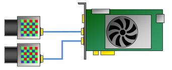
2 1 2 Bayer Pattern Two Cameras, One Port Each, Bayer Pattern
2 1 2 Grayscale Two Cameras, One Port Each, Grayscale
2 1 2 RGB Two Cameras, One Port Each, RGB

To find out which topology you can use with which applet, refer to Choosing the Right Area Scan Applet or Choosing the Right Line Scan Applet.

采集小程序#

To ensure optimum use of system resources, not all image acquisition and processing features designed for marathon ACL are loaded onto marathon ACL simultaneously.

Instead, Basler provides various compilations of specific image acquisition and processing features that are combined to meet the requirements of a specific application field.

Typically, an applet supports a specific camera interface standard and topology, specific image acquisition features, and possibly specific image (pre-)processing features.

Applets come in .dll files.

Refer to Acquisition Applets for marathon ACL for more detailed information about the delivered acquisition applets and their dependency on the topology used.

For PDF documentation of the delivered acquisition applets (GenTL and Fglib), see Acquisition Applets for marathon ACL Documentation.

预防措施#

→ See Safety Instructions (Frame Grabbers).

安装#

→ See Connecting Frame Grabbers.

→ See Connecting Cameras.