Trigger Applications#
Using Multiple Boards#
There are various options to connect and synchronize multiple frame grabbers and trigger boards:
- Connect one trigger board to multiple frame grabbers.
- Connect several trigger boards to one frame grabber. This allows to you, e.g., use the same trigger in two or more different voltage domains.
- Connect multiple frame grabbers without a trigger board: In this case, one master frame grabber synchronizes all its slave frame grabbers.
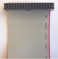
To connect to multiple frame grabber devices, Basler recommends to use a specific 34-pin flat cable (Multi-Board Trigger Cable) provided by Basler. The cable offers one connector for the trigger board and multiple connectors for the frame grabbers. The signals of the cable use open collector drivers.

The Multi-Board Trigger Cable is available in two variants:
- Multi-Board Trigger Cable – Left (order number 2200000374)
- Multi-Board Trigger Cable – Right (order number 2200000480)
Contact Basler Sales for ordering information.
Info
As an alternative to using the multi-board trigger cable, it is also possible to connect and synchronize the frame grabbers via Front GPIO. Basler doesn't provide cables for this purpose.
Using one trigger extension board for several frame grabbers is the easiest solution to synchronize frame grabbers. By sharing the trigger input lines of the trigger board, all frame grabber devices in the computer are synchronized.
There is no limit on how many frame grabber devices can be connected to one trigger extension board. However, Basler recommends connecting only frame grabbers located in the same computer. Usually, a trigger extension board synchronizes all frame grabbers in one computer.
Using a trigger extension board for synchronizing multiple boards is useful if the acquisition is controlled externally.
However, there are applications where no external source is available or desired. In these cases, a master frame grabber device needs to synchronize all its slave frame grabber devices.
Info
Don't connect the following pins between two frame grabbers:
- Pin 2
- Pin 4
- Pin 32
- Pin 34
If you use the Multi-Board Trigger Cable, these lines are already disconnected.
Shaft Encoders#
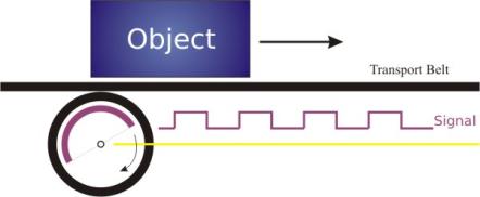
A shaft encoder or rotary encoder can be used to generate trigger input signals for a line camera. A simple relative rotary encoder can only measure the speed of the movement and trigger the camera to sample the object in equidistant lines.
The figure below illustrates a setup where the line camera could, e.g., be triggered on the rising edge of the encoder signal.

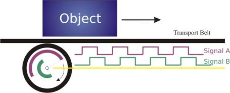
If not only the speed of the object varies, but also the direction of the transport belt (forwards or backwards), a single signal isn't enough to record seamless images. A shaft encoder that allows to detect if the transport belt is moving forwards or backwards has a second encoder signal (signal B), that follows the first signal (signal A) with a certain delay.
The figure below shows an A/B shaft encoder where the line camera could, e.g., be triggered on the edge of the encoder signal A. If the encoder is rotating forwards, then the signal B is low at the moment of the rising signal A.
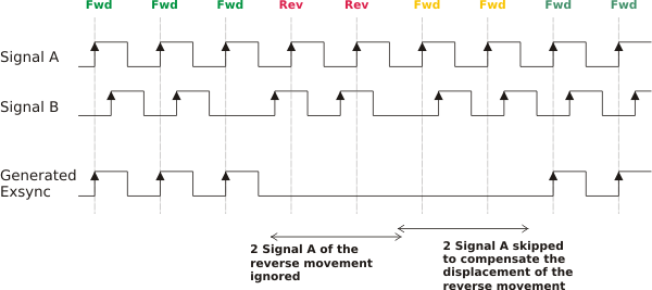
If the encoder is rotating in the other direction, the process is reverted, and signal A follows B. In this case, the signal B is high at a rising signal A, and no trigger signal is generated.

To acquire a seamless image, it's not only necessary to ignore encoder signals generated during backwards rotation, but also to compensate for the "displacement" when moving forward again:

Connecting a Shaft Encoder via Pins (Example)#
You connect the two differential signals (A and B) of the shaft encoder to one of the trigger board ports as follows:

The shaft encoder sends differential signals, i.e., signal A+, signal A-, signal B+, and signal B-. Therefore, you must use four pins (11–14) for receiving two signals (signal A and signal B).
Configuring the Shaft Encoder#
You can configure the shaft encoder via a line scan acquisition applet of your frame grabber. You find the parameter descriptions and instructions you need for this in your line scan acquisition applet documentation of your frame grabber, in chapter Line Trigger / ExSync > ShaftEncoderABFilter: