Serial Communication#
这意味着相机充当主机和另一设备之间的中间 UART 设备。
信息
Serial Communication 功能仅适用于以下 Basler 相机型号:ace 2 R GigE PRO(仅限 1GigE)、ace 2 R USB PRO、dart M 以及 boost R 相机。
该功能的使用#
运作原理#
相机提供两个独立的串行端口 FIFO:一个用于输出 (Tx) 数据,另一个用于输入 (Rx) 数据。为了与主机进行通信,两个 FIFO 都使用一个公共的传输缓冲区。
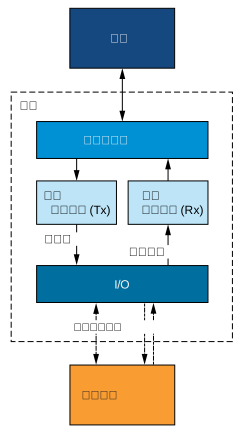
要使用上述接口,必须使用合适的通信协议。协议的具体实施方式取决于您的系统设置和设备的特性。
下面列出了可帮助您执行该协议的相机参数。
配置 Serial Communication#
要配置相机和外部设备之间的串行通信:
- 设置
BslSerialBaudRate参数设置为外部设备的波特率,例如:Baud9600.
信息
如果使用光耦 I/O 线路传输传入 (Rx) 数据,请注意最大波特率限制为 19200 Bd。如果使用光耦 I/O 线路,请将 BslSerialBaudRate 参数相应地进行设置。
- 设置
BslSerialNumberOfDataBits参数设置为外部设备使用的数据位数,例如:Bits8. - 设置
BslSerialNumberOfStopBits参数设置为外部设备使用的停止位数,例如:Bits1. - 设置
BslSerialParity参数设置为外部设备执行的奇偶校验类型,例如:Even. - 配置相机的输入信号。为此,请将
BslSerialRxSource参数设置为要接收串行数据的 I/O 线路,例如:Line2。该线路必须 配置为输入. - 设置
BslSerialTransmitMode参数至HalfDuplex或FullDuplex。该BslSerialTransmitMode参数及其值在 发送参数 部分中的脚注。 - 配置相机的输出信号:
- 设置
LineSelector参数设置为要传输串行数据的 I/O 线路,例如:Line3。该线路必须 配置为输出. - 设置
LineSource参数至SerialTx.
- 设置
测试 Serial Communication#
若要在未将外部设备连接到相机的情况下测试 Serial Communication,或排除由外部设备引起的错误,请将 BslSerialRxSource 参数至 SerialTx.
这会产生回送:串行输入已在内部连接到串行输出,因此相机可以准确接收其传输的内容。
发送和接收数据#
配置串行通信后,可以将数据发送到外部设备并从其接收数据。
信息
如需了解详情,请参阅 pylon API 文档中的 ParametrizeCamera_SerialCommunication (C++) 代码示例。
发送和接收参数#
发送和接收数据均涉及以下参数:
BslSerialTransferBuffer:传输缓冲区保存要传输的数据,同时也包含接收到的数据。它最多可保存 16 个符号。根据BslSerialNumberOfDataBits设置,一个符号由 7 位或 8 位组成。在 GigE 相机上,必须以 DWORD(4 字节的倍数)访问传输缓冲区,即使传输长度不是 4 的倍数也是如此。例如,如果将BslSerialTransferLength参数设置为 9,则每次事务必须从缓冲区读取 12 字节。在 USB 和 CoaXPress 相机上,没有此限制。BslSerialTransferLength:接收时,表示相机在上一次事务期间接收到的符号数。传输时,指定相机每个事务应传输的符号数。最大值为 16。
发送参数#
发送数据涉及以下参数:
BslSerialTransmitMode:此参数决定在相机向外部设备传输数据期间,相机的接收 FIFO (Rx) 是关闭还是开启。如果共享单个 I/O 线路用于传输和接收数据(半双工),相机的接收 FIFO (Rx) 也会接收传输到外部设备的数据。这会非常快速地填满接收 FIFO (Rx)。
设置BslSerialTransmitMode参数至HalfDuplex以在相机向外部设备传输数据期间关闭接收 FIFO (Rx)。这样,只有外部设备传输的数据才会复制到相机的接收 FIFO (Rx) 中。
如果使用两条独立的 I/O 线路,则可以设置BslSerialTransmitMode参数至FullDuplex.BslSerialTransmit:执行此命令可通过串行输出线路传输传输当前的值。这也会更新BslSerialTxFifoEmpty和BslSerialTxFifoOverflowProperty。BslSerialTxFifoEmpty:指示传输 FIFO 是否为空,即相机是否准备好传输数据。BslSerialTxFifoOverflow:指示传输 FIFO 是否溢出。如果将新数据传输到传输 FIFO 的速度快于发送先前数据的速度,即执行BslSerialTransmit命令执行过快。溢出期间发送的数据不会写入传输 FIFO。BslSerialTxBreak:向外部设备发出串行中断信号。如果此参数设置为true,相机将串行输出设置为低电平(space)以发出中断信号。如果此参数设置为false,相机将串行输出重置为高电平(mark)。
接收参数#
接收数据涉及以下参数:
BslSerialReceive:执行此命令可通过串行输入端接收数据。传输完成后,BslSerialTransferBuffer参数包含接收到的数据,BslSerialTransferLength参数指示接收到的有效符号数。此外,执行该命令会更新BslSerialRxFifoOverflow,BslSerialRxParityError和BslSerialRxStopBitError参数的状态。请参见下文。BslSerialRxFifoOverflow:指示接收 FIFO 是否溢出。如果来自外部设备的新数据到达速度快于前一个数据被移至传输缓冲区并发送到主机的速度(即执行BslSerialReceive命令的速度过慢),就会发生溢出。溢出期间接收到的数据将会丢失。BslSerialRxParityError:指示相机是否在接收 FIFO 的数据中检测到奇偶校验错误。如果检测到错误,该参数将保持true状态,直到您通过执行以下操作清空接收 FIFO:BslSerialReceive命令。BslSerialRxStopBitError:指示相机是否在接收 FIFO 的数据中检测到停止位错误。如果检测到错误,该参数将保持true状态,直到您通过执行以下操作清空接收 FIFO:BslSerialReceive命令。BslSerialRxBreak:指示外部设备是否发出了串行中断信号。如果串行输入保持低电平(space)至少 12 个位周期,相机将检测到中断并将该参数设置为true。由于相机无法“预知”中断信号将持续多久,参数值将保持true。要将其重置为false,请确保外部设备已完成发送中断,然后执行BslSerialRxBreakReset命令。BslSerialRxBreakReset:设置BslSerialRxBreak参数至false。参见上文。
示例代码#
// Configure serial communication
// Example: 19200 Baud, 8 data bits, 2 stop bits, even parity
camera.BslSerialBaudRate.SetValue(BslSerialBaudRate_Baud19200);
camera.BslSerialNumberOfDataBits.SetValue(BslSerialNumberOfDataBits_Bits8);
camera.BslSerialNumberOfStopBits.SetValue(BslSerialNumberOfStopBits_Bits2);
camera.BslSerialParity.SetValue(BslSerialParity_Even);
// Configure the camera's input signal
camera.BslSerialRxSource.SetValue(BslSerialRxSource_Line2);
// Configure the camera's output signal
camera.LineSelector.SetValue(LineSelector_Line3);
camera.LineSource.SetValue(LineSource_SerialTx);
// Now, you must implement a suitable communication protocol.
// Camera parameters that help you implement the protocol are listed
// in the "Transmitting and Receiving Data" section above.
INodeMap& nodemap = camera.GetNodeMap();
// Configure serial communication
// Example: 19200 Baud, 8 data bits, 2 stop bits, even parity
CEnumParameter(nodemap, "BslSerialBaudRate").SetValue("Baud19200");
CEnumParameter(nodemap, "BslSerialNumberOfDataBits").SetValue("Bits8");
CEnumParameter(nodemap, "BslSerialNumberOfStopBits").SetValue("Bits2");
CEnumParameter(nodemap, "BslSerialParity").SetValue("Even");
// Configure the camera's input signal
CEnumParameter(nodemap, "BslSerialRxSource").SetValue("Line2");
// Configure the camera's output signal
CEnumParameter(nodemap, "LineSelector").SetValue("Line3");
CEnumParameter(nodemap, "LineSource").SetValue("SerialTx");
// Now, you must implement a suitable communication protocol.
// Camera parameters that help you implement the protocol are listed
// in the "Transmitting and Receiving Data" section above.
// Configure serial communication
// Example: 19200 Baud, 8 data bits, 2 stop bits, even parity
camera.Parameters[PLCamera.BslSerialBaudRate].SetValue(PLCamera.BslSerialBaudRate.Baud19200);
camera.Parameters[PLCamera.BslSerialNumberOfDataBits].SetValue(PLCamera.BslSerialNumberOfDataBits.Bits8);
camera.Parameters[PLCamera.BslSerialNumberOfStopBits].SetValue(PLCamera.BslSerialNumberOfStopBits.Bits2);
camera.Parameters[PLCamera.BslSerialParity].SetValue(PLCamera.BslSerialParity.Even);
// Configure the camera's input signal
camera.Parameters[PLCamera.BslSerialRxSource].SetValue(PLCamera.BslSerialRxSource.Line2);
// Configure the camera's output signal
camera.Parameters[PLCamera.LineSelector].SetValue(PLCamera.LineSelector.Line3);
camera.Parameters[PLCamera.LineSource].SetValue(PLCamera.LineSource.SerialTx);
// Now, you must implement a suitable communication protocol.
// Camera parameters that help you implement the protocol are listed
// in the "Transmitting and Receiving Data" section above.
/* Macro to check for errors */
#define CHECK(errc) if (GENAPI_E_OK != errc) printErrorAndExit(errc)
GENAPIC_RESULT errRes = GENAPI_E_OK;  /* Return value of pylon methods */
/* Configure serial communication */
/* Example: 19200 Baud, 8 data bits, 2 stop bits, even parity */
errRes = PylonDeviceFeatureFromString(hdev, "BslSerialBaudRate", "Baud19200");
CHECK(errRes);
errRes = PylonDeviceFeatureFromString(hdev, "BslSerialNumberOfDataBits", "Bits8");
CHECK(errRes);
errRes = PylonDeviceFeatureFromString(hdev, "BslSerialNumberOfStopBits", "Bits2");
CHECK(errRes);
errRes = PylonDeviceFeatureFromString(hdev, "BslSerialParity", "Even");
CHECK(errRes);
/* Configure the camera's input signal */
errRes = PylonDeviceFeatureFromString(hdev, "BslSerialRxSource", "Line2");
CHECK(errRes);
/* Configure the camera's output signal */
errRes = PylonDeviceFeatureFromString(hdev, "LineSelector", "Line3");
CHECK(errRes);
errRes = PylonDeviceFeatureFromString(hdev, "LineSource", "SerialTx");
CHECK(errRes);
/* Now, you must implement a suitable communication protocol. */
/* Camera parameters that help you implement the protocol are listed */
/* in the "Transmitting and Receiving Data" section above. */
# Configure serial communication
# Example: 19200 Baud, 8 data bits, 2 stop bits, even parity
camera.BslSerialBaudRate.Value = "Baud19200"
camera.BslSerialNumberOfDataBits.Value = "Bits8"
camera.BslSerialNumberOfStopBits.Value = "Bits2"
camera.BslSerialParity.Value = "Even"
# Configure the camera's input signal
camera.BslSerialRxSource.Value = "Line2"
# Configure the camera's output signal
camera.LineSelector.Value = "Line3"
camera.LineSource.Value = "SerialTx"
# Now, you must implement a suitable communication protocol.
# Camera parameters that help you implement the protocol are listed
# in the "Transmitting and Receiving Data" section above.
您也可以使用 pylon Viewer 轻松设置参数。