Encoder Control#
正交编码器也称为增量式编码器、旋转式编码器或轴编码器。它们通常用于需要测量运动或位置变化的自动化应用中。
这Encoder Control 此功能仅适用于Basler racer 2相机。
该功能的使用#
运作原理#
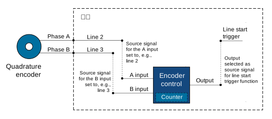
这Encoder Control 它与正交编码器连接,该编码器可以是旋转式或线性式,产生两个输出信号 A 和 B。这两个信号也称为相位信号或源信号 A 和 B。这两个信号具有 90° 的相位差,用于跟踪编码器的前后运动方向。相位信号 A 和 B 是摄像机编码器控制的输入信号。
下图展示了编码器控制的典型实现方式。
Encoder Direction of Motion#
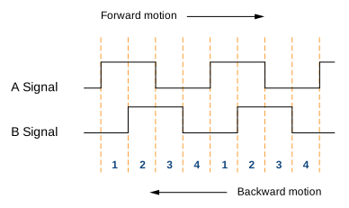
编码器可以向前或向后移动。为了检测运动方向,编码器控制器读取A信号和B信号上升沿和下降沿的顺序。
- 前进方向: A信号比B信号提前90°上升。相位顺序为1-2-3-4。
- 运动方向相反: B信号先于A信号上升。相位顺序为4-3-2-1。
下图显示了与 A 信号和 B 信号的数字信号电平相对应的四个相位。
位置Counter#
编码器控制采用由A和B信号驱动的位置计数器。计数器值在运动向前方向递增,在运动向后方向递减。
位置计数器持续运行。其数值表示自上次重置以来接收到的信号数量。因此,计数器值始终反映目标物体相对于前进或后退运动方向的当前位置。
Encoder Mode#
编码器模式控制编码器控制器如何计算输入的编码器信号。
Four Phase Mode#
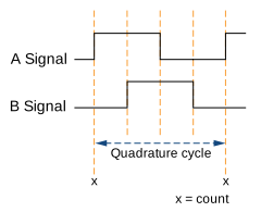
四个完整的信号相位构成一个正交周期。每个完整的正交周期,即当 A 信号边沿上升时,正交编码器计数器加 1 或减 1。
四相模式非常稳健,可以滤除两相之间少量的信号抖动。
High Resolution Mode#
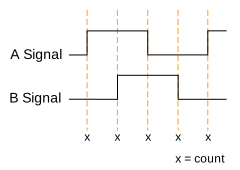
在高分辨率模式下,每个周期的计数增加到原来的四倍。编码器计数器在每个信号相位上递增或递减 1,即当 A和B 信号的边沿上升沿和下降沿时。
信息
高分辨率模式下无法进行抖动滤波。因此,不建议将高分辨率模式与以下情况一起使用: 编码器输出模式 设置为 Motion 因为两相之间的抖动会导致连续的输出触发脉冲。
Encoder Output Mode#
编码器输出模式允许您设置编码器控制生成有效输出信号的条件。以下是可用的编码器输出模式:
Motion:无论运动方向如何,都会产生输出触发信号。DirectionUp:在所有位置增量处都会生成输出触发信号 向前 方向。运动的反向会被忽略。DirectionDown:在所有位置增量处都会生成输出触发信号 反向 方向。运动的正向会被忽略。PositionUp:在所有 新 位置处生成输出触发信号 向前 方向。如果编码器反向,在重新通过反向开始的位置之前,将不会生成输出触发信号。PositionDown:在所有 新 位置处生成输出触发信号 反向 方向。如果编码器反向,在重新通过反向开始的位置之前,将不会生成输出触发信号。Off:不生成输出触发信号。
附加参数#
EncoderDivider:确定生成编码器输出触发信号所需的来自编码器的输入信号数量。EncoderValue:获取 position counter 的当前值。该 Property 为只读。EncoderReset:将 position counter 的当前计数器值重置为 0。这也将重置并重新启动整个 Encoder Control。重启后立即对信号脉冲进行计数。
配置 Encoder Control#
要配置 Encoder Control:
- 设置
EncoderSelector参数至Encoder1. - 设置
EncoderSourceA将 Property 设置为可用的源信号之一,例如,Line2. - 设置
EncoderSourceB将 Property 设置为可用的源信号之一,例如,Line3. - 设置
EncoderMode参数设置为以下值: - 设置
EncoderDivider将 Property 设置所需的输入信号数量。 - 设置
EncoderOutputMode将 Property 设置为要启用的 output mode 的类型,例如,Motion.
要配置相机由编码器信号触发:
- 设置
TriggerSelector参数至LineStart. - 设置
TriggerMode参数至On. - 设置
TriggerSource参数至Encoder1.
示例代码#
// Select the desired encoder selector
camera.EncoderSelector.SetValue(EncoderSelector_Encoder1)
// Select line 2 as the source signal for the A input of the encoder control
camera.EncoderSourceA.SetValue(EncoderSourceA_Line2);
// Select line 3 as the source signal for the B input of the encoder control
camera.EncoderSourceB.SetValue(EncoderSourceB_Line3);
// Select the desired encoder mode
camera.EncoderMode.SetValue(EncoderMode_FourPhase);
// Determine the number of input signals needed to generate an encoder output trigger signal
camera.EncoderDivider.SetValue(1);
// Select the desired encoder output mode
camera.EncoderOutputMode.SetValue(EncoderOutputMode_Motion);
INodeMap& nodemap = camera.GetNodeMap();
// Select the desired encoder selector
CEnumParameter(nodemap, "EncoderSelector").SetValue("Encoder1");
// Select line 2 as the source signal for the A input of the encoder control
CEnumParameter(nodemap, "EncoderSourceA").SetValue("Line2");
// Select line 3 as the source signal for the B input of the encoder control
CEnumParameter(nodemap, "EncoderSourceB").SetValue("Line3");
// Select the desired encoder mode
CEnumParameter(nodemap, "EncoderMode").SetValue("FourPhase");
// Determine the number of input signals needed to generate an encoder output trigger signal
CIntegerParameter(nodemap, "EncoderDivider").SetValue(1);
// Select the desired encoder output mode
CEnumParameter(nodemap, "EncoderOutputMode").SetValue("Motion");
// Select the desired encoder selector
camera.Parameters[PLCamera.EncoderSelector].SetValue(PLCamera.EncoderSelector.Encoder1);
// Select line 2 as the source signal for the A input of the encoder control
camera.Parameters[PLCamera.EncoderSourceA].SetValue(PLCamera.EncoderSourceA.Line2);
// Select line 3 as the source signal for the B input of the encoder control
camera.Parameters[PLCamera.EncoderSourceB].SetValue(PLCamera.EncoderSourceB.Line3);
// Select the desired encoder mode
camera.Parameters[PLCamera.EncoderMode].SetValue(PLCamera.EncoderMode.FourPhase);
// Determine the number of input signals needed to generate an encoder output trigger signal
camera.Parameters[PLCamera.EncoderDivider].SetValue(1);
// Select the desired encoder output mode
camera.Parameters[PLCamera.EncoderOutputMode].SetValue(PLCamera.EncoderOutputMode.Motion);
/* Macro to check for errors */
#define CHECK(errc) if (GENAPI_E_OK != errc) printErrorAndExit(errc)
GENAPIC_RESULT errRes = GENAPI_E_OK;  /* Return value of pylon methods */
/* Select the desired encoder selector */
errRes = PylonDeviceFeatureFromString(hdev, "EncoderSelector", "Encoder1");
CHECK(errRes);
/* Select line 2 as the source signal for the A input of the encoder control */
errRes = PylonDeviceFeatureFromString(hdev, "EncoderSourceA", "Line2");
CHECK(errRes);
/* Select line 3 as the source signal for the B input of the encoder control */
errRes = PylonDeviceFeatureFromString(hdev, "EncoderSourceB", "Line3");
CHECK(errRes);
/* Select the desired encoder mode */
errRes = PylonDeviceFeatureFromString(hdev, "EncoderMode", "FourPhase");
CHECK(errRes);
/* Determine the number of input signals needed to generate an encoder output trigger signal */
errRes = PylonDeviceSetIntegerFeature(hdev, "EncoderDivider", 1);
CHECK(errRes);
/* Select the desired encoder output mode */
errRes = PylonDeviceFeatureFromString(hdev, "EncoderOutputMode", "Motion");
CHECK(errRes);
# Select the desired encoder selector
camera.EncoderSelector.Value = "Encoder1"
# Select line 2 as the source signal for the A input of the encoder control
camera.EncoderSourceA.Value = "Line2"
# Select line 3 as the source signal for the B input of the encoder control
camera.EncoderSourceB.Value = "Line3"
# Select the desired encoder mode
camera.EncoderMode.Value = "FourPhase"
# Determine the number of input signals needed to generate an encoder output trigger signal
camera.EncoderDivider.Value = 1
# Select the desired encoder output mode
camera.EncoderOutputMode.Value = "Motion"
您也可以使用 pylon Viewer 轻松设置参数。