pylon SDK Samples Manual#
Overview#
The pylon Software Suite includes an SDK with the following APIs:
- pylon Data Processing API for C++ (Windows, Linux)
- pylon API for C++ (Windows, Linux, and macOS)
- pylon API for C (Windows and Linux)
- pylon API for .NET languages, e.g., C# and VB.NET (Windows only)
Along with the APIs, the pylon Software Suite also includes a set of sample programs and documentation.
- On Windows operating systems, the source code for the samples can be found here:
<pylon installation directory>\Basler\pylon 7\Development\Samples
Example: C:\Program Files\Basler\pylon 7\Development\Samples - On Linux or macOS operating systems, the source code for the samples can be copied from the archive to any location on the target computer.
For more information about programming using the pylon API, see the pylon API Documentation section.
Data Processing API for C++ (Windows, Linux)#
Barcode#
This sample demonstrates how to use the Barcode vTool. The Barcode vTool requires a valid evaluation license or runtime license.
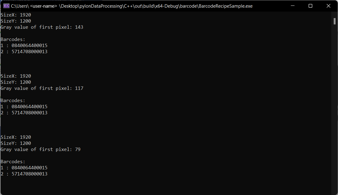
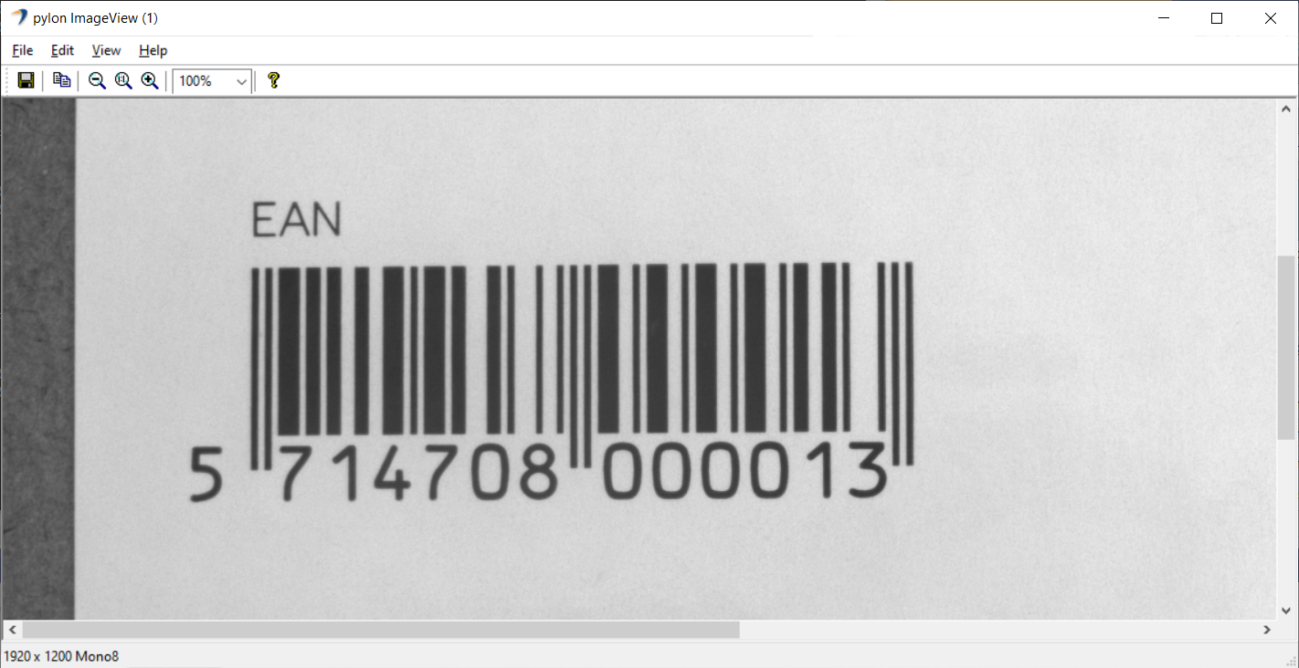
This sample uses a predefined barcode.precipe file, the pylon camera emulation, and sample images to demonstrate reading of up to two barcodes of an EAN type.
Code#
The MyOutputObserver class is used to create a helper object that shows how to handle output data provided via the IOutputObserver::OutputDataPush interface method. Also, MyOutputObserver shows how a thread-safe queue can be implemented for later processing while pulling the output data.
The CRecipe class is used to create a recipe object representing a recipe file that is created using the pylon Viewer Workbench.
The recipe.Load() method is used to load a recipe file.
The recipe.PreAllocateResources() method allocates all needed resources, e.g., it opens the camera device and allocates buffers for grabbing.
The recipe.RegisterAllOutputsObserver() method is used to register the MyOutputObserver object, which is used for collecting the output data, e.g., barcodes.
The recipe.Stop() method is called to stop the processing.
Applicable Interfaces#
- GigE Vision
- USB3 Vision
- CXP
BuildersRecipe#
This sample demonstrates how to create and modify recipes programmatically.
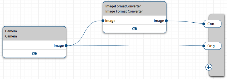
For demonstration purposes, this sample creates a recipe that contains a Camera vTool and an Image Format Converter vTool and sets up connections between the vTools and the recipe's output terminal.
Code#
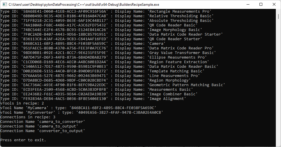
The CBuildersRecipe class is used to query the type IDs of all vTool types available in your setup using the recipe.GetAvailableVToolTypeIDs() method. Using recipe.GetVToolDisplayNameForTypeID(), the vTools' display names are printed to the console.
The recipe.AddVTool() method is used to add vTools to the recipe with a string identifier using the vTool's type ID.
Info
While recipe.GetAvailableVToolTypeIDs() lists the type IDs of all vTools installed on your system, recipe.AddVTool() only allows you to add vTools for which you have the correct license. If you use recipe.AddVTool() with the type ID of a vTool without the correct license, the method will throw an exception.
The recipe.HasVTool() method can be used to check whether the recipe contains a vTool with a given identifier.
To get a list of the identifiers of all vTools in a recipe, the recipe.GetVToolIdentifiers() method is used.
The recipe.GetVToolTypeID() method is used to get the type ID of a vTool instance by its identifier.
The recipe.AddOutput() method is used to add two image outputs to the recipe.
The recipe.AddConnection() method is used to create the following connections:
- Connect the Image output of the Camera vTool to the Image input of the Image Format Converter vTool.
- Connect the Image output of the Camera vTool to an input of the recipe's output terminal called "OriginalImage".
- Connect the Image output of the Image Format Converter vTool to an input of the recipe's output terminal called "ConvertedImage".
The recipe.GetConnectionIdentifiers() method is used to get the identifiers of all connections in the recipe and to print them to the console.
The CBuildersRecipe class can be used like the CRecipe class to run the recipe that has been created.
The recipe.Start() method is called to start the processing.
The recipe.Stop() method is called to stop the processing.
Applicable Interfaces#
- GigE Vision
- USB3 Vision
- CXP
Camera#
This sample demonstrates how to use and parametrize the Camera vTool. The Camera vTool doesn't require a license.
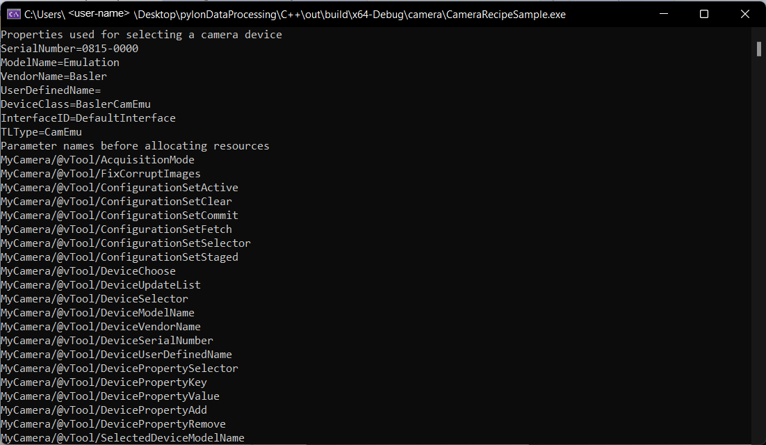
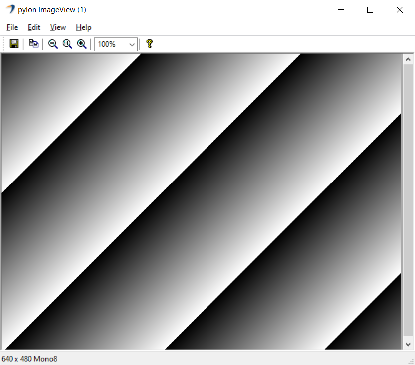
This sample uses a predefined camera.precipe file and the pylon Camera Emulation for demonstration purposes.
Code#
The MyOutputObserver class is used to create a helper object that shows how to handle output data provided via the IOutputObserver::OutputDataPush interface method. Also, MyOutputObserver shows how a thread-safe queue can be implemented for later processing while pulling the output data.
The CRecipe class is used to create a recipe object that represents a recipe file created using the pylon Viewer Workbench.
The recipe.Load() method is used to load a recipe file. After loading the recipe, some Pylon::CDeviceInfo properties of the camera are accessed and displayed on the console for demonstration purposes.
The recipe.PreAllocateResources() method allocates all needed resources, e.g., it opens the camera device and allocates buffers for grabbing. After opening the camera device, some camera parameters are read out and printed for demonstration purposes.
The recipe.RegisterAllOutputsObserver() method is used to register the MyOutputObserver object, which is used for collecting the output data, e.g., images.
The recipe.Stop() method is called to stop the processing.
The recipe.DeallocateResources() method is called to free all used resources.
Applicable Interfaces#
- GigE Vision
- USB3 Vision
- CXP
Chunks#
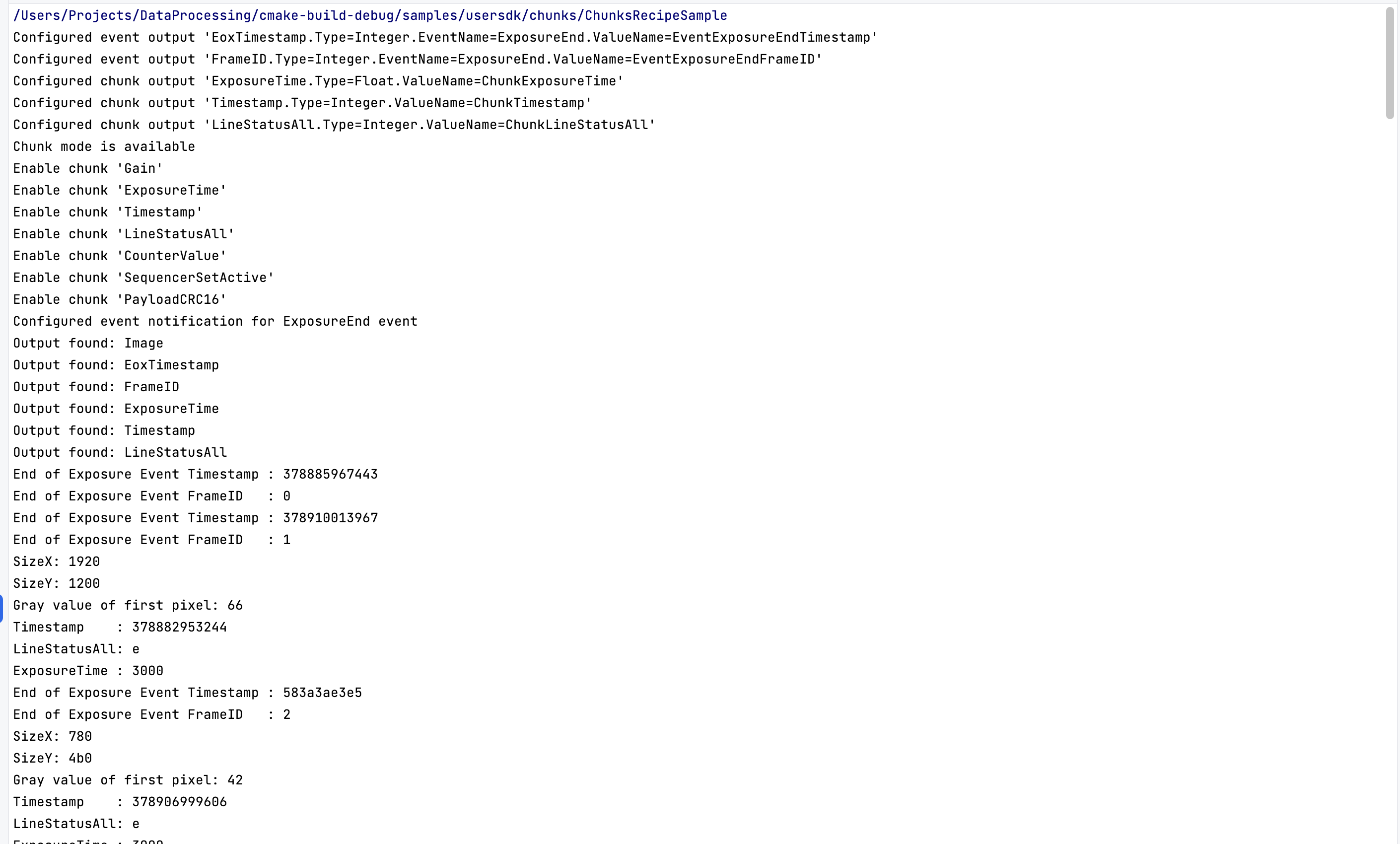
The Chunks and Events Sample demonstrates how turn on the Data Chunks and Event Notifications camera features in order to receive chunks and events from the Camera vTool and to output their data using dynamic pins. The Chunks and Events vTool doesn't require a license.
This sample extends the Camera sample.
Code#
"EoxTimestamp.Type=Integer.EventName=ExposureEnd.ValueName=EventExposureEndTimestamp",
"FrameID.Type=Integer.EventName=ExposureEnd.ValueName=EventExposureEndFrameID"
"ExposureTime.Type=Float.ValueName=ChunkExposureTime",
"Timestamp.Type=Integer.ValueName=ChunkTimestamp",
"LineStatusAll.Type=Integer.ValueName=ChunkLineStatusAll"
ValueName defines the feature to read. Type is the data type used for the output. The first item EoxTimeStamp in the example above, is the name of the pin.
Dynamic pins should be configured before allocating resources.
The camera is selected, and its node map is created when resources are allocated. Now, the camera has to be configured.
The sample program checks whether the camera selected supports chunk data. If so, the chunk data will be output together with the image data. Here, the chunks are selected in the node map one by one and are enabled. Depending on the camera model, different chunks are available.
Finally, the program tries to turn the generation of the Exposure End event on.
A generic output observer is attached to the recipe, and then the recipe is started. It runs until one hundred results (also called updates) have been collected and prints the values.
If chunks or events aren't supported, the program prints a warning message.
Applicable Interfaces#
- GigE Vision
- USB3 Vision
- CXP
Composite Data Types#
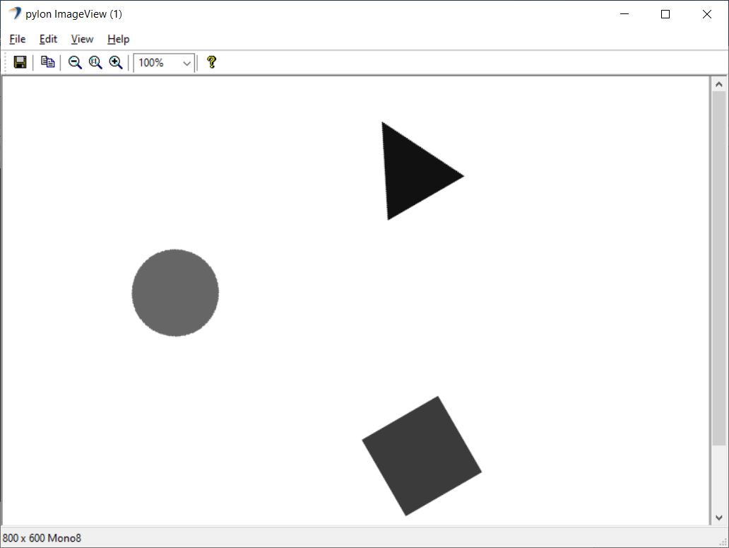
This sample demonstrates how to use vTools that output composite data types, e.g., Absolute Thresholding, Region Morphology, Region Feature Extraction, etc. These vTools require a valid evaluation license or runtime license. Data types like PointF or RectangleF are composite data types.
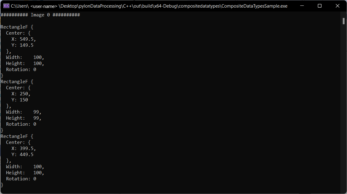
This sample obtains information about the composition, e.g., RectangleF, and accesses the data, e.g., Center X, Center Y, Width, Height, and Rotation, by using a predefined composite_data_types.precipe file, the pylon camera emulation, and sample images. It depends on the input or output terminal pin(s), depending on whether image coordinates in pixels and world coordinates in meters are used.
Code#
The RectangleF struct in the ResultData class is used to store the data of the composite data type.
The MyOutputObserver class is used to create a helper object that shows how to handle output data provided via the IOutputObserver::OutputDataPush interface method. Also, MyOutputObserver shows how a thread-safe queue can be implemented for later processing while pulling the output data.
The CVariant and the GetSubValue() show how to access the data of composite data types of RectangleF.
The CRecipe class is used to create a recipe object that represents a recipe file created using the pylon Viewer Workbench.
The recipe.Load() method is used to load a recipe file.
The recipe.PreAllocateResources() method allocates all needed resources, e.g., it opens the camera device and allocates buffers for grabbing.
The recipe.RegisterAllOutputsObserver() method is used to register the MyOutputObserver object, which is used for collecting the output data, e.g., images and composite data types.
The recipe.Stop() method is called to stop the processing.
With the recipe.DeallocateResources() method you can free all used resources.
Applicable Interfaces#
- GigE Vision
- USB3 Vision
- CXP
OCR#
This sample demonstrates how to use the OCR Basic vTool. The OCR Basic vTool requires a valid evaluation license or runtime license.
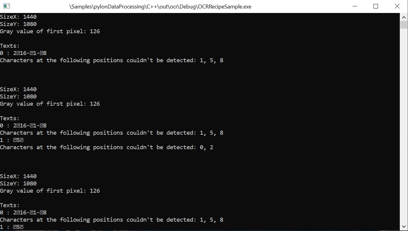
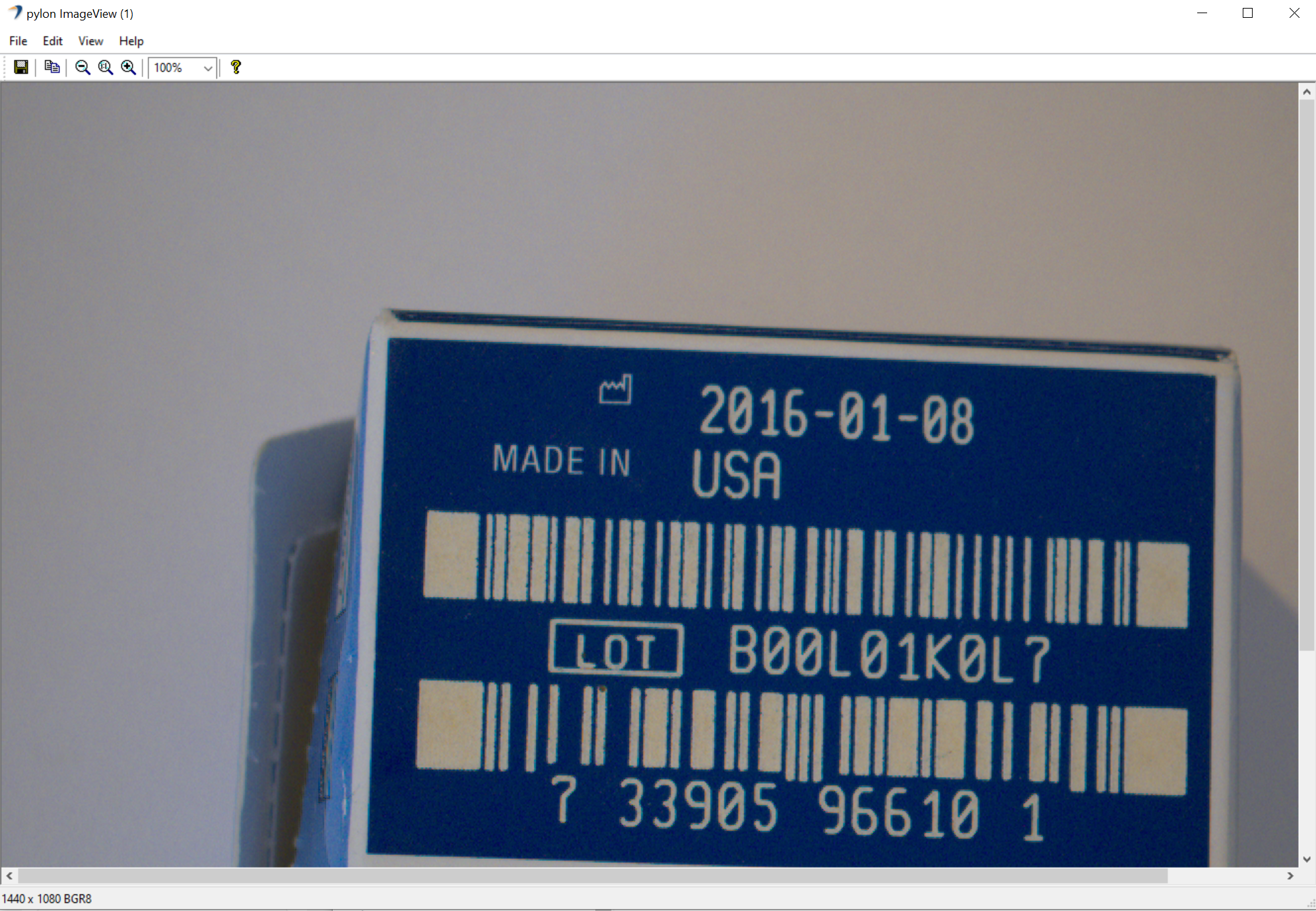
This sample uses a predefined ocr.precipe file as well as the Image Loading, Geometric Pattern Matching Basic, Image Alignment and OCR Basic vTools and sample images to demonstrate detecting characters in images.
Code#
The CGenericOutputObserver class is used to receive the output data from the recipe.
The CRecipe class is used to create a recipe object representing a recipe file that is created using the pylon Viewer Workbench.
The recipe.Load() method is used to load a recipe file.
The SourcePath parameter of the Image Loading vTool is set to provide the path to the sample images to the vTool.
The recipe.RegisterAllOutputsObserver() method is used to register the CGenericOutputObserver object, which is used for collecting the output data.
The recipe.Start() method is called to start the processing.
For each result received, the image dimensions and gray value of the first pixel are printed to the console.
Additionally, all detected characters are printed to the console. Characters that couldn't be detected are marked by the UTF-8 rejection character.
After half of the images have been processed, the character set of the OCR Basic vTool is changed to All. This results in all characters being detected.
The recipe.Stop() method is called to stop the processing.
Applicable Interfaces#
- GigE Vision
- USB3 Vision
- CXP
Region#
This sample demonstrates how to use the CRegion data type.
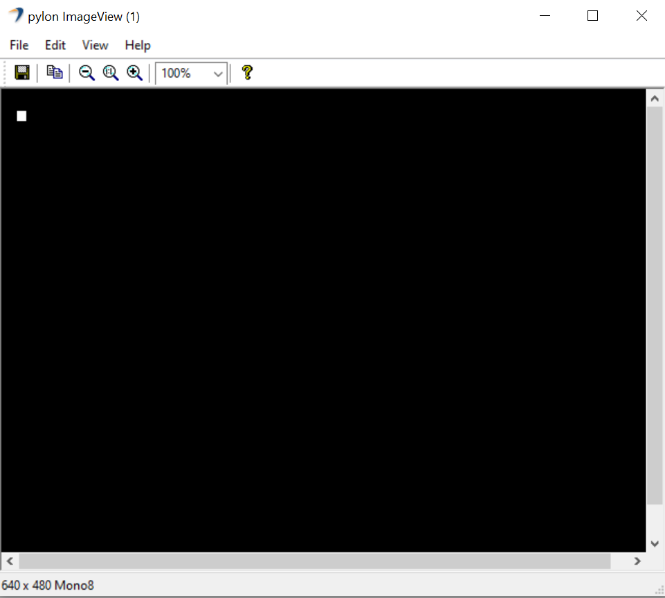
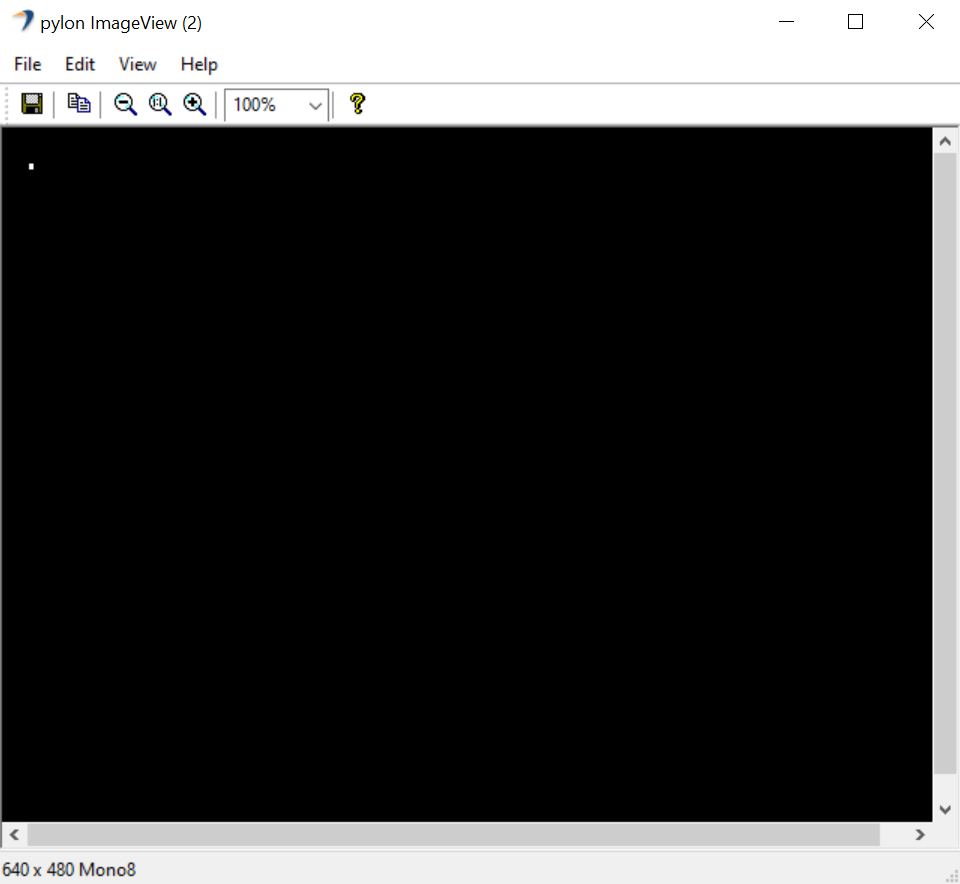
This sample uses a predefined region.precipe file and the Region Morphology vTool to demonstrate how to create CRegion objects and how to access their attributes.
The following image shows the region created manually.
This image shows the region output by the Region Morphology vTool.
Code#
The CGenericOutputObserver class is used to receive the output data from the recipe.
The CRecipe class is used to create a recipe object representing a recipe file that is created using the pylon Viewer Workbench.
The recipe.Load() method is used to load a recipe file.
The recipe.RegisterAllOutputsObserver() method is used to register the CGenericOutputObserver object, which is used for collecting the output data.
The ComputeRegionSize() function is used compute the required size in bytes to store ten run-length-encoded region entries.
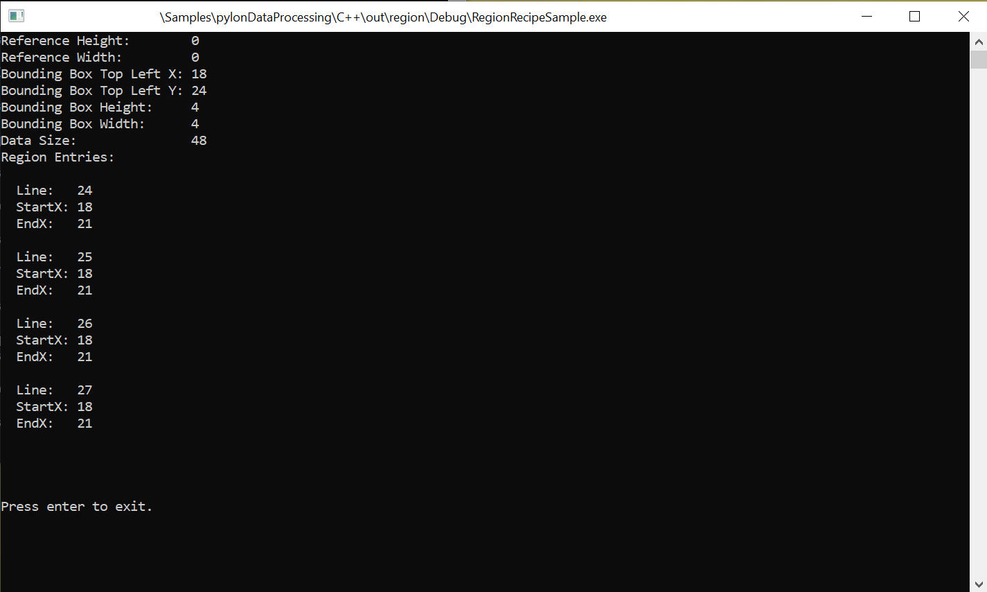
A CRegion object is created with a data size large enough to store ten region entries, a reference size of 640 * 480 pixels, and a bounding box starting at the pixel position X=15, Y=21 with a height of 10 pixels and a width of 10 pixels.
To access the individual region entries, the region buffer is accessed using the region.GetBuffer() method.
Each run-length-encoded region entry is defined by a start X position and an end X Position and a Y position. These are set for all entries in a loop.
The attributes of the region created are queried using the inputRegion.GetReferenceHeight(), inputRegion.GetReferenceWidth(), inputRegion.GetBoundingBoxTopLeftX(), inputRegion.GetBoundingBoxTopLeftY(), inputRegion.GetBoundingBoxHeight(), inputRegion.GetBoundingBoxWidth(), and inputRegion.GetDataSize() methods and then printed to the console.
The recipe.Start() method is called to start the processing.
The region created is pushed to the recipe's input pin called Regions using the recipe.TriggerUpdate() method.
The resultCollector.RetrieveResult() method is used to retrieve the processed results.
The attributes of all resulting regions and their region entries are printed to the console.
The recipe.Stop() method is called to stop the processing.
Applicable Interfaces#
- GigE Vision
- USB3 Vision
- CXP
C++ Samples#
DeviceRemovalHandling#
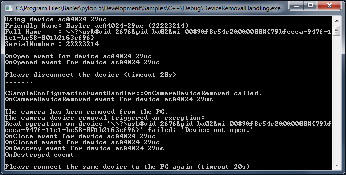
This sample demonstrates how to detect the removal of a camera device. It also shows you how to reconnect to a removed device.
Info
If you build this sample in debug mode and run it using a GigE camera device, pylon will set the heartbeat timeout to 5 minutes. This is done to allow debugging and single-stepping without losing the camera connection due to missing heartbeats. However, with this setting, it would take 5 minutes for the application to notice that a GigE device has been disconnected. As a workaround, the heartbeat timeout is set to 1000 ms.
Code#
Info
You can find the sample code here.
The CTlFactory class is used to create a generic transport layer.
The CInstantCamera class is used to create an Instant Camera object with the first camera device found.
The CHeartbeatHelper class is used to set the HeartbeatTimeout to an appropriate value.
The CSampleConfigurationEventHandler is used to handle device removal events.
Applicable Interfaces#
- GigE Vision
- USB3 Vision
- Camera Link
Grab#
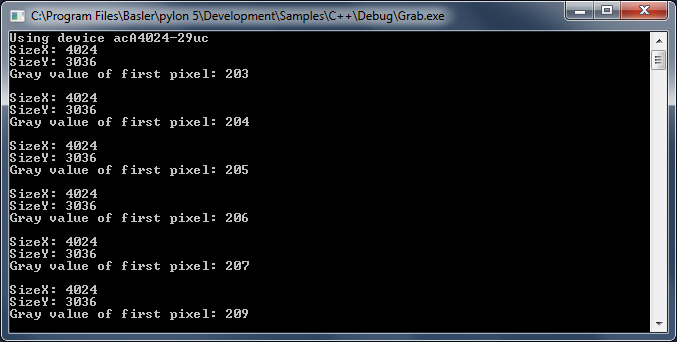
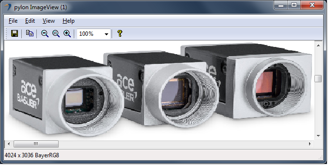
This sample demonstrates how to grab and process images using the CInstantCamera class.
The images are grabbed and processed asynchronously, i.e., at the same time that the application is processing a buffer, the acquisition of the next buffer takes place.
The CInstantCamera class uses a pool of buffers to retrieve image data from the camera device. Once a buffer is filled and ready, the buffer can be retrieved from the camera object for processing. The buffer and additional image data are collected in a grab result. The grab result is held by a smart pointer after retrieval. The buffer is automatically reused when explicitly released or when the smart pointer object is destroyed.
Code#
Info
You can find the sample code here.
The CInstantCamera class is used to create an Instant Camera object with the first camera device found.
The CGrabResultPtr class is used to initialize a smart pointer that will receive the grab result data. It controls the reuse and lifetime of the referenced grab result. When all smart pointers referencing a grab result go out of scope, the referenced grab result is reused or destroyed. The grab result is still valid after the camera object it originated from has been destroyed.
The DisplayImage class is used to display the grabbed images.
Applicable Interfaces#
- GigE Vision
- USB3 Vision
- CXP
Grab_CameraEvents#
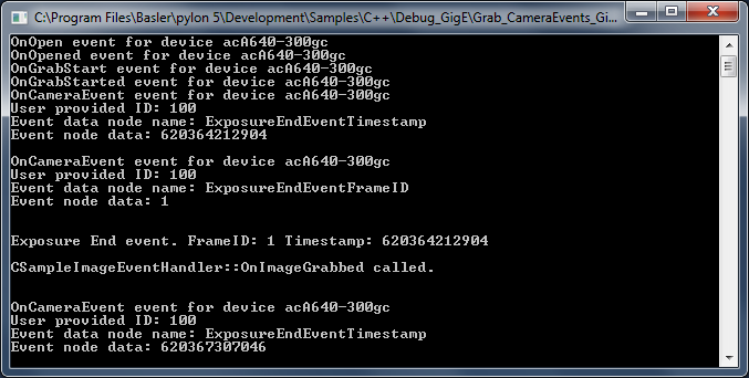
Basler USB3 Vision and GigE Vision cameras can send event messages. For example, when a sensor exposure has finished, the camera can send an Exposure End event to the computer. The event can be received by the computer before the image data of the finished exposure has been transferred completely. This sample demonstrates how to be notified when camera event message data is received.
The event messages are automatically retrieved and processed by the InstantCamera classes. The information carried by event messages is exposed as parameter nodes in the camera node map and can be accessed like standard camera parameters. These nodes are updated when a camera event is received. You can register camera event handler objects that are triggered when event data has been received.
These mechanisms are demonstrated for the Exposure End and the Event Overrun events.
The Exposure End event carries the following information:
- ExposureEndEventFrameID: Number of the image that has been exposed.
- ExposureEndEventTimestamp: Time when the event was generated.
- ExposureEndEventStreamChannelIndex: Number of the image data stream used to transfer the image. On Basler cameras, this parameter is always set to 0.
The Event Overrun event is sent by the camera as a warning that events are being dropped. The notification contains no specific information about how many or which events have been dropped.
Events may be dropped if events are generated at a high frequency and if there isn't enough bandwidth available to send the events.
This sample also shows you how to register event handlers that indicate the arrival of events sent by the camera. For demonstration purposes, different handlers are registered for the same event.
Info
Different camera families implement different versions of the Standard Feature Naming Convention (SFNC). That's why the name and the type of the parameters used can be different.
Code#
Info
You can find the sample code here.
The CBaslerUniversalInstantCamera class is used to create a camera object with the first camera device found independent of its interface.
The CSoftwareTriggerConfiguration class is used to register the standard configuration event handler for enabling software triggering. The software trigger configuration handler replaces the default configuration handler.
The CSampleCameraEventHandler class demonstrates the use of example handlers for camera events.
The CSampleImageEventHandler class demonstrates the use of an image event handler.
The CGrabResultPtr class is used to initialize a smart pointer that will receive the grab result data. It controls the reuse and lifetime of the referenced grab result. When all smart pointers referencing a grab result go out of scope, the referenced grab result is reused or destroyed. The grab result is still valid after the camera object it originated from has been destroyed.
Applicable Interfaces#
- GigE Vision
- USB3 Vision
Grab_ChunkImage#
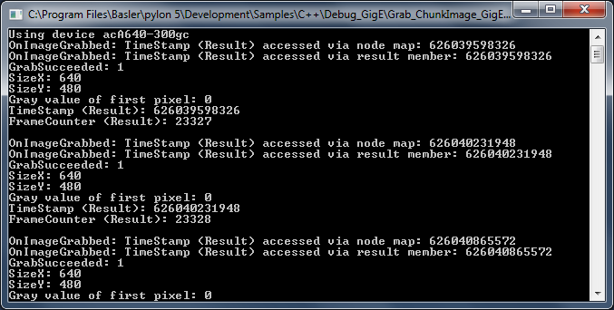
Basler cameras supporting the Data Chunk feature can generate supplementary image data, e.g., frame count, time stamp, or CRC checksums, and append it to each acquired image.
This sample demonstrates how to enable the Data Chunks feature, how to grab images, and how to process the appended data. When the camera is in chunk mode, it transfers data blocks that are partitioned into chunks. The first chunk is always the image data. The data chunks that you have chosen follow the image data chunk.
Code#
Info
You can find the sample code here.
The CBaslerUniversalInstantCamera class is used to create a camera object with the first camera device found independent of its interface.
The CBaslerUniversalGrabResultPtr class is used to initialize a smart pointer that will receive the grab result and chunk data independent of the camera interface.
The CSampleImageEventHandler class demonstrates the use of an image event handler.
The DisplayImage class is used to display the grabbed images.
Applicable Interfaces#
- GigE Vision
- USB3 Vision
Grab_MultiCast#
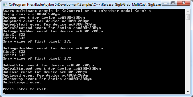
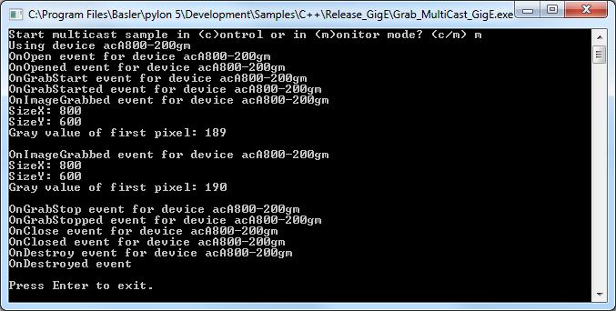
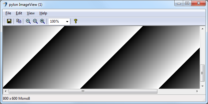
This sample applies to Basler GigE Vision cameras only and demonstrates how to open a camera in multicast mode and how to receive a multicast stream.
Two instances of an application must be run simultaneously on different computers. The first application started on computer A acts as the controlling application and has full access to the GigE camera. The second instance started on computer B opens the camera in monitor mode. This instance is not able to control the camera but can receive multicast streams.
To run the sample, start the application on computer A in control mode. After computer A has begun to receive frames, start the second instance of this application on computer B in monitor mode.
Code#
Info
You can find the sample code here.
The CDeviceInfo class is used to look for cameras with a specific interface, i.e., GigE Vision only (BaslerGigEDeviceClass).
The CBaslerUniversalInstantCamera class is used to find and create a camera object for the first GigE camera found.
When the camera is opened in control mode, the transmission type must be set to "multicast". In this case, the IP address and the IP port must also be set. This is done by the following command:
camera.GetStreamGrabberParams().TransmissionType = TransmissionType_Multicast;
When the camera is opened in monitor mode, i.e., the camera is already controlled by another application and configured for multicast, the active camera configuration can be used. In this case, the IP address and IP port will be set automatically:
camera.GetStreamGrabberParams().TransmissionType = TransmissionType_UseCameraConfig;
RegisterConfiguration() is used to remove the default camera configuration. This is necessary when a monitor mode is selected because the monitoring application is not allowed to modify any camera parameter settings.
The CConfigurationEventPrinter and CImageEventPrinter classes are used for information purposes to print details about events being called and image grabbing.
The CGrabResultPtr class is used to initialize a smart pointer that will receive the grab result data. It controls the reuse and lifetime of the referenced grab result. When all smart pointers referencing a grab result go out of scope, the referenced grab result is reused or destroyed. The grab result is still valid after the camera object it originated from has been destroyed.
Applicable Interfaces#
- GigE Vision
Grab_MultipleCameras#
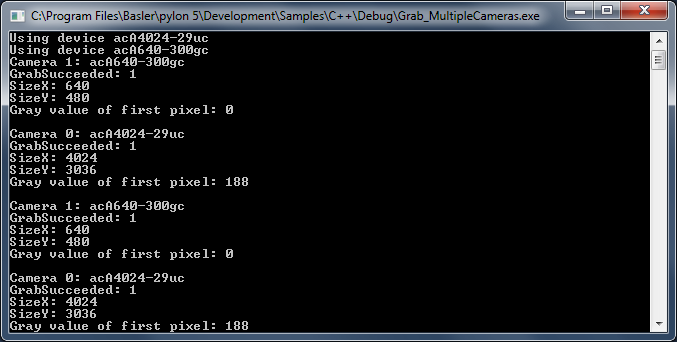
This sample demonstrates how to grab and process images from multiple cameras using the CInstantCameraArray class. The CInstantCameraArray class represents an array of Instant Camera objects. It provides almost the same interface as the Instant Camera for grabbing.
The main purpose of CInstantCameraArray is to simplify waiting for images and camera events of multiple cameras in one thread. This is done by providing a single RetrieveResult method for all cameras in the array.
Alternatively, the grabbing can be started using the internal grab loop threads of all cameras in the CInstantCameraArray. The grabbed images can then be processed by one or more image event handlers. Note that this is not shown in this sample.
Code#
Info
You can find the sample code here.
The CInstantCameraArray class demonstrates how to create an array of Instant Cameras for the devices found.
StartGrabbing() starts grabbing sequentially for all cameras, starting with index 0, 1, etc.
The CGrabResultPtr class is used to initialize a smart pointer that will receive the grab result data. It controls the reuse and lifetime of the referenced grab result. When all smart pointers referencing a grab result go out of scope, the referenced grab result is reused or destroyed. The grab result is still valid after the camera object it originated from has been destroyed.
The DisplayImage class is used to show the image acquired by each camera in a separate window for each camera.
Applicable Interfaces#
- GigE Vision
- USB3 Vision
- CXP
Grab_Strategies#
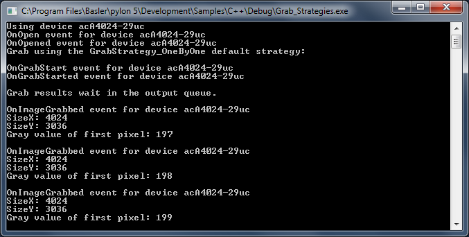
This sample demonstrates the use of the following CInstantCamera grab strategies:
- GrabStrategy_OneByOne
- GrabStrategy_LatestImageOnly
- GrabStrategy_LatestImages
- GrabStrategy_UpcomingImage
When the "OneByOne" grab strategy is used, images are processed in the order of their acquisition. This strategy can be useful when all grabbed images need to be processed, e.g., in production and quality inspection applications.
The "LatestImageOnly" and "LatestImages" strategies can be useful when the acquired images are only displayed on screen. If the processor has been busy for a while and images could not be displayed automatically, the latest image is displayed when processing time is available again.
The "UpcomingImage" grab strategy can be used to make sure to get an image that has been grabbed after RetrieveResult() has been called. This strategy cannot be used with USB3 Vision cameras.
Code#
Info
You can find the sample code here.
The CInstantCamera class is used to create an Instant Camera object with the first camera device found.
The CGrabResultPtr class is used to initialize a smart pointer that will receive the grab result data. It controls the reuse and lifetime of the referenced grab result. When all smart pointers referencing a grab result go out of scope, the referenced grab result is reused or destroyed. The grab result is still valid after the camera object it originated from has been destroyed.
The CSoftwareTriggerConfiguration class is used to register the standard configuration event handler for enabling software triggering. The software trigger configuration handler replaces the default configuration. StartGrabbing() is used to demonstrate the usage of the different grab strategies.
Applicable Interfaces#
- GigE Vision
- USB3 Vision
- CXP
Grab_UsingActionCommand#
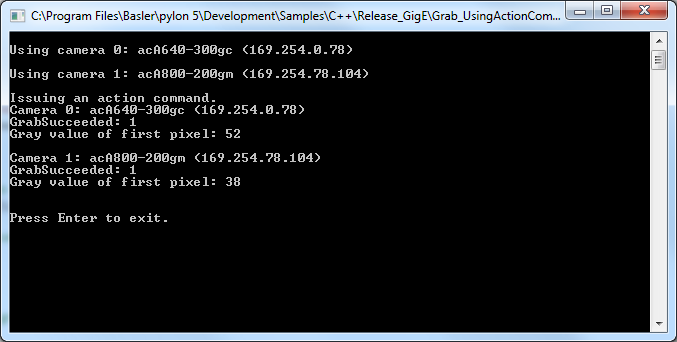
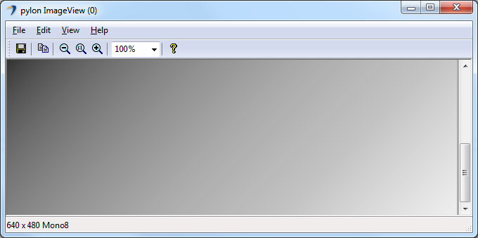
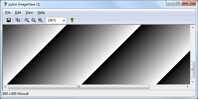
This sample applies to Basler GigE Vision cameras only and demonstrates how to issue a GigE Vision ACTION_CMD to multiple cameras.
By using an action command, multiple cameras can be triggered at the same time as opposed to software triggering where each camera must be triggered individually.
Code#
Info
You can find the sample code here.
To make the configuration of multiple cameras easier, this sample uses the CBaslerUniversalInstantCameraArray class.
The IGigETransportLayer interface is used to issue action commands.
The CActionTriggerConfiguration class is used to set up the basic action command features.
The CBaslerUniversalGrabResultPtr class is used to declare and initialize a smart pointer to receive the grab result data. When the cameras in the array are created, a camera context value is assigned to the index number of the camera in the array. The camera context is a user-settable value, which is attached to each grab result and can be used to determine the camera that produced the grab result, i.e., ptrGrabResult->GetCameraContext().
The DisplayImage class is used to display the grabbed images.
Applicable Interfaces#
- GigE Vision
Grab_UsingAsyncGatedTriggerMultiframe#
The sample demonstrates how to use Overflow events and asynchronous gated triggers (Multiframe) in line scan applications where you want to capture images that are composed of a sequence of multiple buffers. This sample applies when using software triggering.
Typically, this is useful in applications where a gate is used to mark the end of an image, e.g., a light barrier is used to determine whether there is an object on a conveyor belt or whether the conveyor belt is empty. This results in the camera being triggered and the lines being appended on the frame grabber.
Using the image ROI parameters, you can specify the buffer size. For example, you can set the width and the height to 8192.
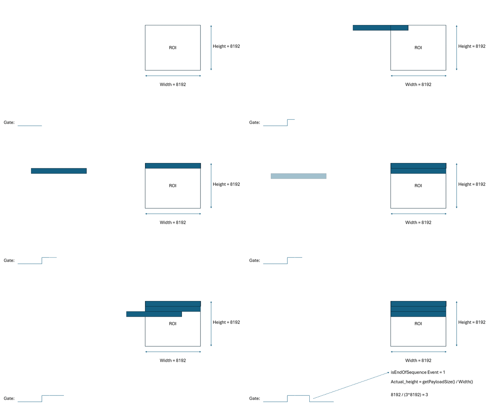
In this example, the signal at the gate is high for 3 lines. So, three lines should be combined on the frame grabber to form one image. Because the buffer is larger than this (8192 x 8192), you must use GetPayloadSize() to determine the actual height of the image in order to reconstruct it correctly.
The following animation shows this example.
If the signal at the gate were high for 16384 lines, however, this would cause RAM usage and latency to increase so much that inspection tasks become virtually impossible.
For cases like this, you can define a smaller ROI, e.g., 8192 x 1024. This would result in several images that all belong to one sequence. For example, if the signal at the gate is high for 5000 lines, you will get 5 images, where the first four have a height of 1024 and the last one a height of 904.
Again, it is necessary to calculate the actual height by using the GetPayloadSize() method. Furthermore, to know whether the images belong to the same sequence, the isEndOfSequence event must be read out.
The following animation shows a simplified version of this scenario with the height set to 2.
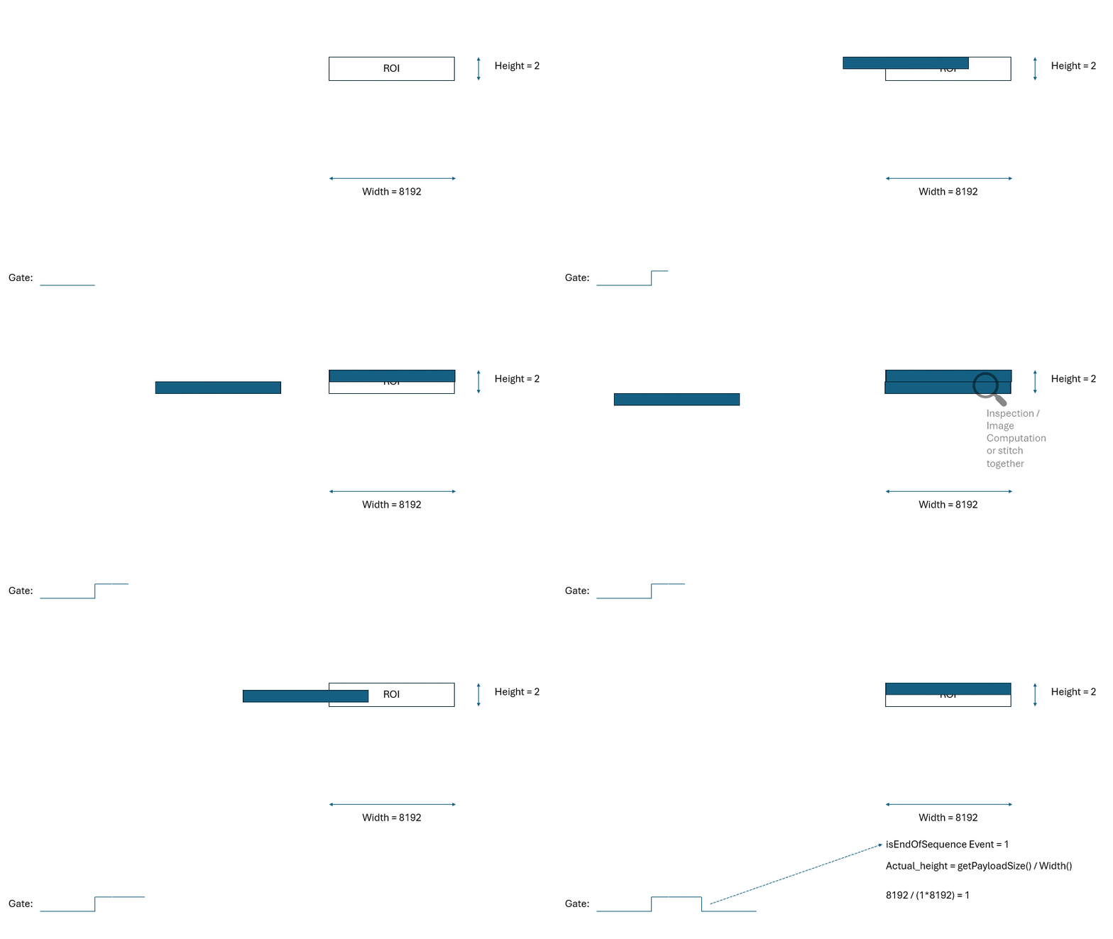
For this event, it is necessary to register a callback event. Because this event is in the frame grabber, it is also necessary to call the unregister function manually to make it thread-safe.
Configuring the Camera#
- Create and open a camera.
- Set the
TestPatternenumeration node to pattern6. - Set
AutomaticROIControltoOff. - Set the
EventSelectortransport layer node to theOverflowevent. - Set the
EventNotificationtransport layer node toOnto enable event notifications for overflows on the frame grabber. - Set the
OverflowEventSelecttransport layer node toAllto get notifications for all events. - Set the
ImageTriggerModetransport layer node toAsyncGatedTriggerMultiframe. - Set the
ImageTriggerInputSourcetransport layer node toSoftwareTrigger. - Set the
SetSoftwareTriggertransport layer node to0. - Start grabbing on the camera.
Event Handling Callback#
- If grabbing is not terminated, get the pNode parameter's children.
- If the node name is
EventOverflowFrameId, store the frame ID. - If the node name is
EventOverflowIsEndOfSequencestore the sequence end.
Key Transport Layer Parameters#
| Node | Purpose |
|---|---|
| EventSelector | Sets the event notification to be enabled. |
| EventNotification | Enables event notifications for the event currently selected by the EventSelector node. |
| OverflowEventSelect | Sets which overflow events result in notifications. |
| ImageTriggerMode | Sets the image trigger mode, e.g., AsyncGatedTriggerMultiframe, AsyncGatedTrigger, AsyncExternalTriggerMultiframe. |
Applicable Interfaces#
- CXP
Grab_UsingAsyncGatedTriggerMultiframe_Hardware#
The sample demonstrates how to use Overflow events and asynchronous gated triggers (Multiframe) in line scan applications where you want to capture images that are composed of a sequence of multiple buffers. This sample applies when using hardware triggering.
Typically, this is useful in applications where a gate is used to mark the end of an image, e.g., a light barrier is used to determine whether there is an object on a conveyor belt or whether the conveyor belt is empty. This results in the camera being triggered and the lines being appended on the frame grabber.
Using the image ROI parameters, you can specify the buffer size. For example, you can set the width and the height to 8192.
In this example, the signal at the gate is high for 3 lines. So, three lines should be combined on the frame grabber to form one image. Because the buffer is larger than this (8192 x 8192), you must use GetPayloadSize() to determine the actual height of the image in order to reconstruct it correctly.
The following animation shows this example.

If the signal at the gate were high for 16384 lines, however, this would cause RAM usage and latency to increase so much that inspection tasks become virtually impossible.
For cases like this, you can define a smaller ROI, e.g., 8192 x 1024. This would result in several images that all belong to one sequence. For example, if the signal at the gate is high for 5000 lines, you will get 5 images, where the first four have a height of 1024 and the last one a height of 904.
Again, it is necessary to calculate the actual height by using the GetPayloadSize() method. Furthermore, to know whether the images belong to the same sequence, the isEndOfSequence event must be read out.
The following animation shows a simplified version of this scenario with the height set to 2.

For this event, it is necessary to register a callback event. Because this event is in the frame grabber, it is also necessary to call the unregister function manually to make it thread-safe.
Configuring the Camera#
- Create and open a camera.
- Set the
TestPatternenumeration node to pattern6. - Set
AutomaticROIControltoOff. - Set the
EventSelectortransport layer node to theOverflowevent. - Set the
EventNotificationtransport layer node toOnto enable event notifications for overflows on the frame grabber. - Set the
OverflowEventSelecttransport layer node toAllto get notifications for all events. - Register the event notification callback at the
EventOverflowDatatransport layer node. - Set the
ImageTriggerModetransport layer node toAsyncGatedTriggerMultiframe. - Set the
LineSelectornode to line2andLineModetoInputon the camera. - Set the
LineSelectornode to line2andLineModetoInputon the camera. - Set the
TriggerSelectornode toLineStartandTriggerModetoOnon the camera. - Set the
ImageTriggerInputSourcetransport layer node toTriggerInSourceFrontGPI3. - Start grabbing on the camera.
Event Handling Callback#
- If grabbing is not terminated, get the pNode parameter's children.
- If the node name is
EventOverflowFrameId, store the frame ID. - If the node name is
EventOverflowIsEndOfSequencestore the sequence end.
Key Transport Layer Parameters#
| Node | Purpose |
|---|---|
| EventSelector | Sets the event notification to be enabled. |
| EventNotification | Enables event notifications for the event currently selected by the EventSelector node. |
| OverflowEventSelect | Sets which overflow events result in notifications. |
| ImageTriggerMode | Sets the image trigger mode, e.g., AsyncGatedTriggerMultiframe, AsyncGatedTrigger, AsyncExternalTriggerMultiframe. |
Applicable Interfaces#
- CXP
Grab_UsingBufferFactory#
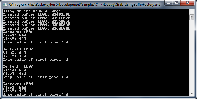
This sample demonstrates the use of a user-provided buffer factory.
The use of a buffer factory is optional and intended for advanced use cases only. A buffer factory is only required if you plan to grab into externally supplied buffers.
Code#
Info
You can find the sample code here.
The MyBufferFactory class demonstrates the use of a user-provided buffer factory.
The buffer factory must be created first because objects on the stack are destroyed in reverse order of creation. The buffer factory must exist longer than the Instant Camera object in this sample.
The CInstantCamera class is used to create an Instant Camera object with the first camera device found.
SetBufferFactory() provides its own implementation of a buffer factory. Since we control the lifetime of the factory object, we pass the Cleanup_None argument.
Applicable Interfaces#
- GigE Vision
- USB3 Vision
- CXP
Grab_UsingExposureEndEvent#
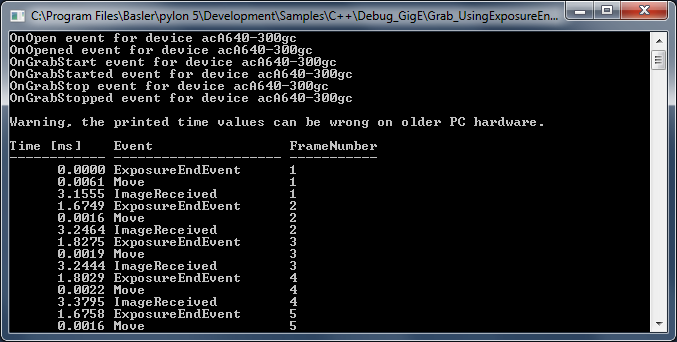
This sample demonstrates how to use the Exposure End event to speed up image acquisition.
For example, when a sensor exposure is finished, the camera can send an Exposure End event to the computer.
The computer can receive the event before the image data of the finished exposure has been transferred completely.
This can be used in order to avoid an unnecessary delay, e.g., when an imaged object is moved before the related image data transfer is complete.
Code#
Info
You can find the sample code here.
The MyEvents enumeration is used for distinguishing between different events, e.g., ExposureEndEvent, FrameStartOvertrigger, EventOverrunEvent, ImageReceivedEvent, MoveEvent, NoEvent.
The CEventHandler class is used to register image and camera event handlers.
Info
Additional handling is required for GigE camera events because the event network packets can be lost, doubled or delayed on the network.
The CBaslerUniversalInstantCamera class is used to create a camera object with the first camera device found independent of its interface.
The CConfigurationEventPrinter class is used for information purposes to print details about camera use.
The CGrabResultPtr class is used to initialize a smart pointer that will receive the grab result data. It controls the reuse and lifetime of the referenced grab result. When all smart pointers referencing a grab result go out of scope, the referenced grab result is reused or destroyed. The grab result is still valid after the camera object it originated from has been destroyed.
Applicable Interfaces#
- GigE Vision
- USB3 Vision
Grab_UsingGrabLoopThread#
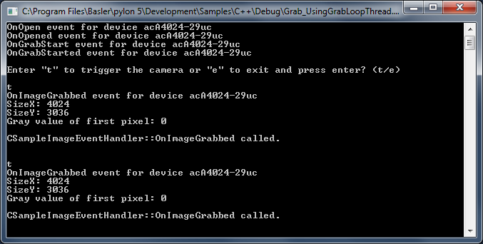
This sample demonstrates how to grab and process images using the grab loop thread provided by the CInstantCamera class.
Code#
Info
You can find the sample code here.
The CInstantCamera class is used to create an Instant Camera object with the first camera device found.
The CSoftwareTriggerConfiguration class is used to register the standard configuration event handler for enabling software triggering. The software trigger configuration handler replaces the default configuration.
The CConfigurationEventPrinter class is used for information purposes to print details about camera use.
The CImageEventPrinter class serves as a placeholder for an image processing task. When using the grab loop thread provided by the Instant Camera object, an image event handler processing the grab results must be created and registered.
CanWaitForFrameTriggerReady() is used to query the camera device whether it is ready to accept the next frame trigger.
StartGrabbing() demonstrates how to start grabbing using the grab loop thread by setting the grabLoopType parameter to GrabLoop_ProvidedByInstantCamera. The grab results are delivered to the image event handlers. The "OneByOne" default grab strategy is used in this case.
WaitForFrameTriggerReady() is used to wait up to 500 ms for the camera to be ready for triggering.
ExecuteSoftwareTrigger() is used to execute the software trigger.
The DisplayImage class is used to display the grabbed images.
Applicable Interfaces#
- GigE Vision
- USB3 Vision
- CXP
Grab_UsingOverflowEvent#
This sample combines software triggering with evaluation of Overflow events on Basler CXP frame grabbers. Images are acquired asynchronously by CInstantCamera, and each grab result is matched with the corresponding EventOverflowFrameId/EventOverflowIsEndOfSequence tag so the application knows precisely when a gated multiframe sequence has finished.
Configuring the Camera#
- Initialise pylon, create the first available device, and open it.
- Configure the following the parameters on the camera and the frame grabber:
TestPattern=6AutomaticROIControl=falseWidth/HeightImageTriggerMode=AsyncGatedTriggerMultiframeImageTriggerInputSource=SoftwareTriggerSetSoftwareTrigger=LowActive
- Enable Overflow events:
- Set
EventSelectortoOverflow - Set
EventNotificationtoOn. - Set
OverflowEventSelecttoAll.
- Set
- Register callback for
EventOverflowData.
The handler extractsEventOverflowFrameIdandEventOverflowIsEndOfSequenceand stores them in a thread‑safe list. - Start grabbing (
StartGrabbing(count)) and run a background task that retrieves eachCGrabResultPtr, aligns it with the oldest pending tag, and prints diagnostics. - Send ten software triggers by toggling
SetSoftwareTriggerin a loop. - Wait for the grab loop to finish, deregister the callback, and terminate pylon.
Key Transport Layer Parameters#
| Node | Purpose |
|---|---|
| EventSelector | Sets the event notification to be enabled. |
| EventNotification | Enables event notifications for the event currently selected by the EventSelector node. |
| OverflowEventSelect | Sets which overflow events result in notifications. |
| ImageTriggerMode | Sets the image trigger mode, e.g., AsyncGatedTriggerMultiframe. |
| ImageTriggerInputSource | Sets the trigger input source. |
| SetSoftwareTrigger | Sets the polarity that enables the trigger. |
Applicable Interfaces#
- CXP
Grab_UsingSequencer#
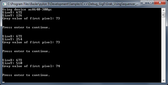
This sample demonstrates how to grab images using the Sequencer feature of a Basler camera.
Three sequence sets are used for image acquisition. Each sequence set uses a different image height.
Code#
Info
You can find the sample code here.
The CBaslerUniversalInstantCamera class is used to create a camera object with the first camera device found independent of its interface.
The CSoftwareTriggerConfiguration class is used to register the standard configuration event handler for enabling software triggering. The software trigger configuration handler replaces the default configuration.
The CGrabResultPtr class is used to initialize a smart pointer that will receive the grab result data. It controls the reuse and lifetime of the referenced grab result. When all smart pointers referencing a grab result go out of scope, the referenced grab result is reused or destroyed. The grab result is still valid after the camera object it originated from has been destroyed.
The DisplayImage class is used to display the grabbed images.
Applicable Interfaces#
- GigE Vision
- USB3 Vision
GUI_ImageWindow#
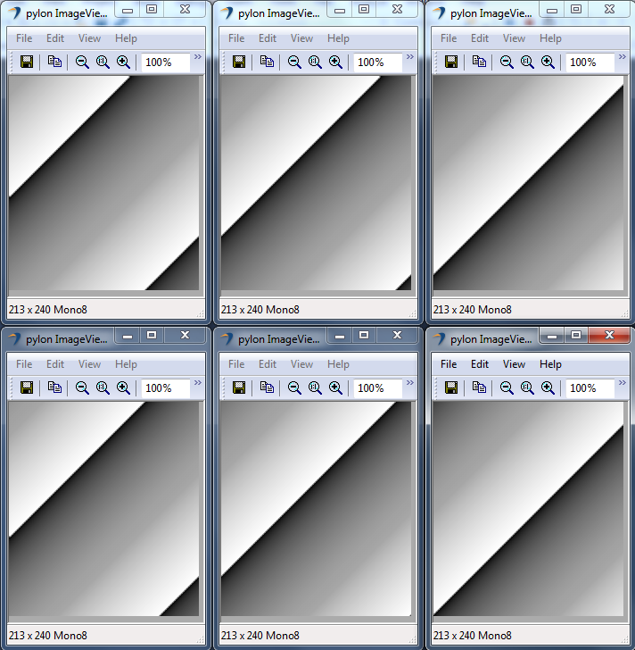
This sample demonstrates how to display images using the CPylonImageWindow class. Here, an image is grabbed and split into multiple tiles. Each tile is displayed in a separate image window.
Code#
Info
You can find the sample code here.
The CPylonImageWindow class is used to create an array of image windows for displaying camera image data.
The CInstantCamera class is used to create an Instant Camera object with the first camera device found.
StartGrabbing() demonstrates how to start the grabbing by applying the GrabStrategy_LatestImageOnly grab strategy. Using this strategy is recommended when images have to be displayed.
The CGrabResultPtr class is used to initialize a smart pointer that will receive the grab result data. It controls the reuse and lifetime of the referenced grab result. When all smart pointers referencing a grab result go out of scope, the referenced grab result is reused or destroyed. The grab result is still valid after the camera object it originated from has been destroyed.
The CPylonImage class is used to split the grabbed image into tiles, which in turn will be displayed in different image windows.
Applicable Interfaces#
- GigE Vision
- USB3 Vision
- CXP
GUI_Sample#
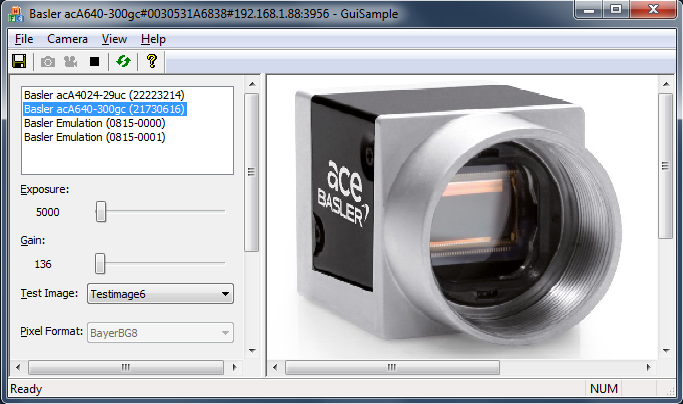
This sample demonstrates the use of a MFC GUI together with the pylon C++ API to enumerate attached cameras, to configure a camera, to start and stop the grab and to display and store grabbed images.
It also shows you how to use GUI controls to display and modify camera parameters.
Code#
Info
You can find the sample code here.
When the Refresh button is clicked, CGuiSampleDoc::OnViewRefresh() is called, which in turn calls CGuiSampleApp::EnumerateDevices() to enumerate all attached devices.
By selecting a camera in the device list, CGuiSampleApp::OnOpenCamera() is called to open the selected camera. The Single Shot (Grab One) and Start (Grab Continuous) buttons as well as the Exposure, Gain, Test Image, and Pixel Format parameters are initialized and enabled now.
By clicking the Single Shot button, CGuiSampleDoc::OnGrabOne() is called. To grab a single image, StartGrabbing() is called with the following arguments:
m_camera.StartGrabbing(1, Pylon::GrabStrategy_OneByOne, Pylon::GrabLoop_ProvidedByInstantCamera);
When the image is received, pylon will call the CGuiSampleDoc::OnImageGrabbed() handler. To display the image, CGuiSampleDoc::OnNewGrabresult() is called.
By clicking the Start button, CGuiSampleDoc::OnStartGrabbing() is called.
To grab images continuously, StartGrabbing() is called with the following arguments:
m_camera.StartGrabbing(Pylon::GrabStrategy_OneByOne, Pylon::GrabLoop_ProvidedByInstantCamera);
In this case, the camera will grab images until StopGrabbing() is called.
When a new image is received, pylon will call the CGuiSampleDoc::OnImageGrabbed() handler. To display the image, CGuiSampleDoc::OnNewGrabresult() is called.
The Stop button gets enabled only after the Start button has been clicked. To stop continuous image acquisition, the Stop button has to be clicked. Upon clicking the Stop button, CGuiSampleDoc::OnStopGrab() is called.
When the Save button is clicked, CGuiSampleDoc::OnFileImageSaveAs() is called and a Bitmap (BMP) image will be saved (BMP is the default file format). Alternatively, the image can be saved in TIFF, PNG, JPEG, or Raw file formats.
Applicable Interfaces#
- GigE Vision
- USB3 Vision
- CXP
GUI_SampleMultiCam#
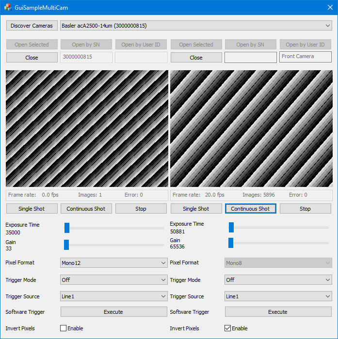
This sample demonstrates how to operate multiple cameras using an MFC GUI together with the pylon C++ API.
The sample demonstrates different techniques for opening a camera, e.g., by using its serial number or user device ID. It also contains an image processing example and shows how to handle device disconnections.
The sample covers single and continuous image acquisition using software as well as hardware triggering.
Code#
Info
You can find the sample code here.
When the Discover Cameras button is clicked, the CGuiSampleMultiCamDlg::OnBnClickedButtonScan() function is called, which in turn calls the CGuiSampleMultiCamDlg::EnumerateDevices() function to enumerate all attached devices.
By clicking the Open Selected button, the CGuiSampleMultiCamDlg::InternalOnBnClickedOpenSelected() function is called, which in turn calls the CGuiSampleMultiCamDlg::InternalOpenCamera() function to create a new device info object
Then, the CGuiCamera::CGuiCamera() function is called to create a camera object and open the selected camera. In addition, callback functions for parameter changes are registered, e.g., for Exposure Time, Gain, Pixel Format, etc.
Cameras can be opened by clicking the Open by SN (SN = serial number) or Open by User ID button. The latter assumes that you have already assigned a user ID to the camera, e.g., in the pylon Viewer or via the pylon API.
After a camera has been opened, the following GUI elements become available:
- Single Shot, Continuous Shot, Stop, and Execute (for executing a software trigger) buttons
- Exposure Time and Gain sliders
- Pixel Format, Trigger Mode, and Trigger Source drop-down lists
- Invert Pixels check box
By clicking the Single Shot button, the CGuiCamera::SingleGrab() function is called. To grab a single image, the StartGrabbing() function is called with the following arguments:
m_camera.StartGrabbing(1, Pylon::GrabStrategy_OneByOne, Pylon::GrabLoop_ProvidedByInstantCamera);
When the image is received, pylon will call the CGuiCamera::OnImageGrabbed() handler. To display the image, the CGuiSampleMultiCamDlg::OnNewGrabresult() function is called.
By clicking the Continuous Shot button, the CGuiCamera::ContinuousGrab() function is called. To grab images continuously, the StartGrabbing() function is called with the following arguments:
m_camera.StartGrabbing(Pylon::GrabStrategy_OneByOne, Pylon::GrabLoop_ProvidedByInstantCamera);
In this case, the camera will grab images until StopGrabbing() is called.
When a new image is received, pylon will call the CGuiCamera::OnImageGrabbed() handler. To display the image, the CGuiSampleMultiCamDlg::OnNewGrabresult() function is called.
This sample also demonstrates the triggering of cameras by using a software trigger. For this purpose, the Trigger Mode parameter has to be set to On, and the Trigger Source parameter has to be set to Software. When starting a single or a continuous image acquisition, the camera will then be waiting for a software trigger.
By clicking the Execute button, the CGuiCamera::ExecuteSoftwareTrigger() function will be called, which will execute a software trigger.
For triggering the camera by hardware trigger, set Trigger Mode to On and Trigger Source to, e.g., Line1. When starting a single or a continuous image acquisition, the camera will then be waiting for a hardware trigger.
By selecting the Invert Pixels check box, an example of image processing will be shown. In the example, the pixel data will be inverted. This is done in the CGuiCamera::OnNewGrabResult() function.
Finally, this sample also shows the use of Device Removal callbacks. If an already opened camera is disconnected, the CGuiCamera::OnCameraDeviceRemoved() function is called. In turn, the CGuiSampleMultiCamDlg::OnDeviceRemoved() function will be called to inform the user about the disconnected camera.
Applicable Interfaces#
- GigE Vision
- USB3 Vision
- CoaXPres
GUI_QtMultiCam#
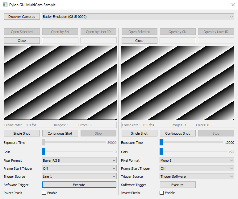
This sample demonstrates how to operate multiple cameras using a Qt GUI together with the pylon C++ API.
Info
An installation of Qt Creator 5.12 or newer and a Microsoft Visual C++ Compiler is required.
The sample demonstrates different techniques for opening a camera, e.g., by using its serial number or user device ID. It also contains an image-processing example and shows how to handle device disconnections.
The sample covers single and continuous image acquisition using software as well as hardware triggering.
Code#
When you click the Discover Cameras button, the MainDialog::on_scanButton_clicked() function is called, which in turn calls the MainDialog::EnumerateDevices() function to enumerate all attached devices.
By clicking the Open Selected button, the MainDialog::on_openSelected_1_clicked() or the MainDialog::on_openSelected_2_clicked() function is called, which in turn calls the CGuiCamera::Open() function to create a camera object and to open the selected camera. In addition, callback functions for parameter changes are registered, e.g., for Exposure Time, Gain, Pixel Format, etc.
Cameras can be opened by clicking the Open by SN (SN = serial number) or Open by User ID button. The latter assumes that you have already assigned a user ID to the camera, e.g., in the pylon Viewer or via the pylon API.
After a camera has been opened, the following GUI elements become available:
- Single Shot, Continuous Shot, Stop, and Execute (for executing a software trigger) buttons
- Exposure Time and Gain sliders
- Pixel Format, Trigger Mode, and Trigger Source drop-down lists
- Invert Pixels check box
By clicking the Single Shot button, the CGuiCamera::SingleGrab() function is called. To grab a single image, the StartGrabbing() function is called with the following arguments:
m_camera.StartGrabbing(1, Pylon::GrabStrategy_OneByOne, Pylon::GrabLoop_ProvidedByInstantCamera);
When the image is received, pylon calls the CGuiCamera::OnImageGrabbed() handler.
By clicking the Continuous Shot button, the CGuiCamera::ContinuousGrab() function is called. To grab images continuously, the StartGrabbing() function is called with the following arguments:
m_camera.StartGrabbing(Pylon::GrabStrategy_OneByOne, Pylon::GrabLoop_ProvidedByInstantCamera);
In this case, the camera grabs images until StopGrabbing() is called.
When a new image is received, pylon calls the CGuiCamera::OnImageGrabbed() handler.
This sample also demonstrates the triggering of cameras by using a software trigger. For this purpose, the Trigger Mode parameter has to be set to On, and the Trigger Source parameter has to be set to Software. When starting a single or a continuous image acquisition, the camera then waits for a software trigger.
By clicking the Execute button, the CGuiCamera::ExecuteSoftwareTrigger() function is called, which executes a software trigger.
For triggering the camera by hardware trigger, set Trigger Mode to On and Trigger Source to, e.g., Line1. When starting a single or a continuous image acquisition, the camera then waits for a hardware trigger.
By selecting the Invert Pixels check box, an example of image processing is shown. In the example, the pixel data is inverted. This is done in the CGuiCamera::OnImageGrabbed() function.
Finally, this sample also shows the use of device removal callbacks. If an already opened camera is disconnected, the CGuiCamera::OnCameraDeviceRemoved() function is called. In turn, the MainDialog::OnDeviceRemoved() function is called to inform the user about the disconnected camera.
Applicable Interfaces#
- GigE Vision
- USB3 Vision
- CoaXPress
ParametrizeCamera_AutoFunctions#
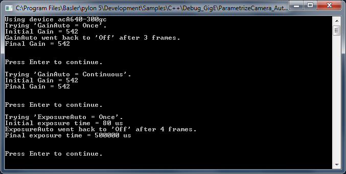
This sample demonstrates how to use the auto functions of Basler cameras, e.g., Gain Auto, Exposure Auto, and Balance White Auto (color cameras only).
Info
Different camera families implement different versions of the Standard Feature Naming Convention (SFNC). That's why the name and the type of the parameters used can be different.
Code#
Info
You can find the sample code here.
The CBaslerUniversalInstantCamera class is used to create a camera object with the first camera device found independent of its interface.
The CAcquireSingleFrameConfiguration class is used to register the standard event handler for configuring single frame acquisition. This overrides the default configuration as all event handlers are removed by setting the registration mode to RegistrationMode_ReplaceAll. Note that the camera device auto functions do not require grabbing by single frame acquisition. All available acquisition modes can be used.
The AutoGainOnce() and AutoGainContinuous() functions control brightness by using the Once and the Continuous modes of the Gain Auto auto function.
The AutoExposureOnce() and AutoExposureContinuous() functions control brightness by using the Once and the Continuous modes of the Exposure Auto auto function.
The CBaslerUniversalGrabResultPtr class is used to initialize a smart pointer that will receive the grab result data. The DisplayImage class is used to display the grabbed images.
Applicable Interfaces#
- GigE Vision
- USB3 Vision
ParametrizeCamera_Configurations#
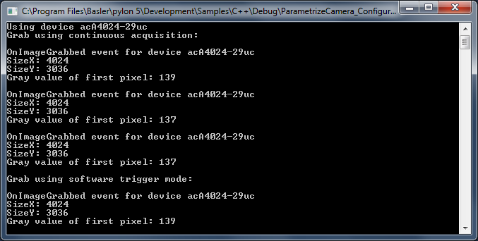
The Instant Camera class provides configuration event handlers to configure the camera and handle grab results. This is very useful for standard camera setups and image processing tasks.
This sample demonstrates how to use the existing configuration event handlers and how to register your own configuration event handlers.
Configuration event handlers are derived from the CConfigurationEventHandler base class. This class provides virtual methods that can be overridden. If the configuration event handler is registered, these methods are called when the state of the Instant Camera object changes, e.g., when the camera object is opened or closed.
The standard configuration event handler provides an implementation for the OnOpened() method that parametrizes the camera.
To override Basler's implementation, create your own handler and attach it to CConfigurationEventHandler.
Device-specific camera classes, e.g., for GigE cameras, provide specialized event handler base classes, e.g., CBaslerGigEConfigurationEventHandler.
Code#
Info
You can find the sample code here.
The CInstantCamera class is used to create an Instant Camera object with the first camera device found.
The CImageEventPrinter class is used to output details about the grabbed images.
The CGrabResultPtr class is used to initialize a smart pointer that receives the grab result data. It controls the reuse and lifetime of the referenced grab result. When all smart pointers referencing a grab result go out of scope, the referenced grab result is reused or destroyed. The grab result is still valid after the camera object it originated from has been destroyed.
The CAcquireContinuousConfiguration class is the default configuration of the Instant Camera class. It is automatically registered when an Instant Camera object is created. This Instant Camera configuration is provided as header-only file. The code can be copied and modified to create your own configuration classes.
In this sample, the standard configuration event handler is registered for configuring the camera for continuous acquisition. By setting the registration mode to RegistrationMode_ReplaceAll, the new configuration handler replaces the default configuration handler that has been automatically registered when creating the Instant Camera object. The handler is automatically deleted when deregistered or when the registry is cleared if Cleanup_Delete is specified.
The CSoftwareTriggerConfiguration class is used to register the standard configuration event handler for enabling software triggering. This Instant Camera configuration is provided as header-only file. The code can be copied and modified to create your own configuration classes, e.g., to enable hardware triggering. The software trigger configuration handler replaces the default configuration.
The CAcquireSingleFrameConfiguration class is used to register the standard event handler for configuring single frame acquisition. This overrides the default configuration as all event handlers are removed by setting the registration mode to RegistrationMode_ReplaceAll.
The CPixelFormatAndAoiConfiguration class is used to register an additional configuration handler to set the image format and adjust the image ROI. This Instant Camera configuration is provided as header-only file. The code can be copied and modified to create your own configuration classes.
By setting the registration mode to RegistrationMode_Append, the configuration handler is added instead of replacing the configuration handler already registered.
Applicable Interfaces#
- GigE Vision
- USB3 Vision
- CXP
ParametrizeCamera_GenericParameterAccess#
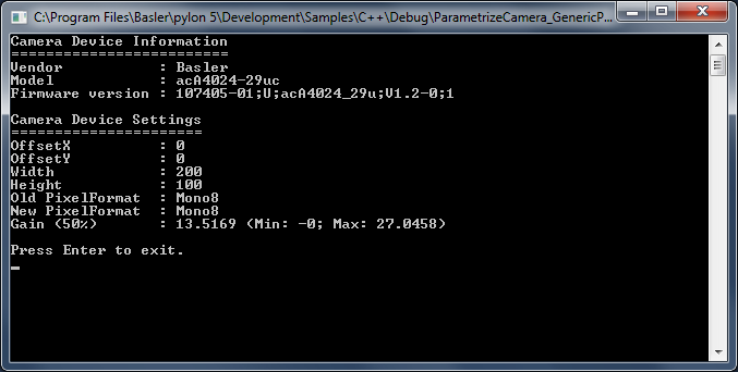
This sample illustrates how to read and write different camera parameter types.
For camera configuration and for accessing other parameters, the pylon API uses the technologies defined by the GenICam standard. The standard also defines a format for camera description files.
These files describe the configuration interface of GenICam-compliant cameras. The description files are written in XML and describe camera registers, their interdependencies, and all other information needed to access high-level features. This includes features such as Gain, Exposure Time, or Pixel Format. The features are accessed by means of low level register read and write operations.
The elements of a camera description file are represented as parameter objects. For example, a parameter object can represent a single camera register, a camera parameter such as Gain, or a set of parameter values. Each node implements the GenApi::INode interface.
The nodes are linked together by different relationships as explained in the GenICam standard document. The complete set of nodes is stored in a data structure called a node map. At runtime, the node map is instantiated from an XML description file.
This sample shows the generic approach for configuring a camera using the GenApi node maps represented by the GenApi::INodeMap interface. The names and types of the parameter nodes can be found in the pylon API Documentation section and by using the pylon Viewer tool.
See also the ParametrizeCamera_NativeParameterAccess sample for the native approach for configuring a camera.
Code#
Info
You can find the sample code here.
The CInstantCamera class is used to create an Instant Camera object with the first camera device found.
The INodeMap interface is used to access the feature node map of the camera device. It provides access to all features supported by the camera.
CIntegerPtr is a smart pointer for the IInteger interface pointer. It is used to access camera features of the int64_t type, e.g., image ROI (region of interest).
CEnumerationPtr is a smart pointer for the IEnumeration interface pointer. It is used to access camera features of the enumeration type, e.g., Pixel Format.
CFloatPtr is a smart pointer for the IFloat interface pointer. It is used to access camera features of the float type, e.g., Gain (only on camera devices compliant with SFNC version 2.0).
Applicable Interfaces#
- GigE Vision
- USB3 Vision
- Camera Link
- CXP
ParametrizeCamera_LoadAndSave#
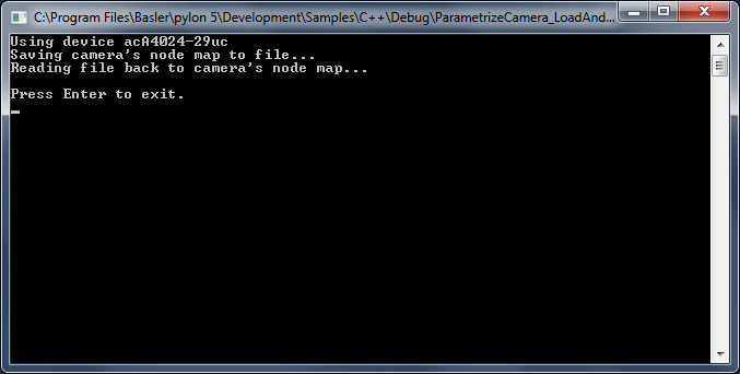
This sample application demonstrates how to save or load the features of a camera to or from a file.
Code#
Info
You can find the sample code here.
The CInstantCamera class is used to create an Instant Camera object with the first camera device found.
The CFeaturePersistence class is a pylon utility class for saving and restoring camera features to and from a file or string.
Info
When saving features, the behavior of cameras supporting sequencers depends on the current setting of the "SequenceEnable" (some GigE models) or "SequencerConfigurationMode" (USB only) features respectively. The sequence sets are only exported, if the sequencer is in configuration mode. Otherwise, the camera features are exported without sequence sets.
Applicable Interfaces#
- GigE Vision
- USB3 Vision
- Camera Link
ParametrizeCamera_LookupTable#
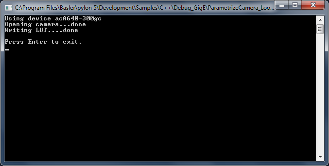
This sample demonstrates the use of the Luminance Lookup Table feature independent of the camera interface.
Code#
Info
You can find the sample code here.
The CBaslerUniversalInstantCamera class is used to create a camera object with the first camera device found independent of its interface.
The camera feature LUTSelector is used to select the lookup table. As some cameras have 10-bit and others have 12-bit lookup tables, the type of the lookup table for the current device must be determined first. The LUTIndex and LUTValue parameters are used to access the lookup table values. This sample demonstrates how the lookup table can be used to cause an inversion of the sensor values.
Applicable Interfaces#
- GigE Vision
- USB3 Vision
ParametrizeCamera_NativeParameterAccess#
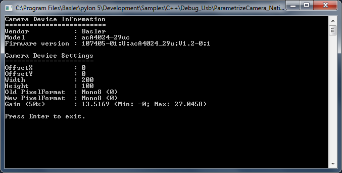
This sample shows the native approach for configuring a camera using device-specific Instant Camera classes. See also the ParametrizeCamera_GenericParameterAccess sample for the generic approach for configuring a camera.
For camera configuration and for accessing other parameters, the pylon API uses the technologies defined by the GenICam standard. The standard also defines a format for camera description files.
These files describe the configuration interface of GenICam-compliant cameras. The description files are written in XML and describe camera registers, their interdependencies, and all other information needed to access high-level features. This includes features such as Gain, Exposure Time, or Pixel Format. The features are accessed by means of low level register read and write operations.
The elements of a camera description file are represented as parameter objects. For example, a parameter object can represent a single camera register, a camera parameter such as Gain, or a set of parameter values. Each node implements the GenApi::INode interface.
Using the code generators provided by GenICam's GenApi module, a programming interface is created from a camera description file. This provides a function for each parameter that is available for the camera device. The programming interface is exported by the device-specific Instant Camera classes. This is the easiest way to access parameters.
Code#
Info
You can find the sample code here.
The CBaslerUniversalInstantCamera class is used to create a camera object with the first camera device found independent of its interface.
This sample demonstrates the use of camera features of the IInteger type, e.g., Width, Height, GainRaw (available on camera devices compliant with SFNC versions before 2.0), of the IEnumeration type, e.g., Pixel Format, or of the IFloat type, e.g., Gain (available on camera devices compliant with SFNC version 2.0).
Applicable Interfaces#
- GigE Vision
- USB3 Vision
- Camera Link
- CXP
ParametrizeCamera_SerialCommunication#
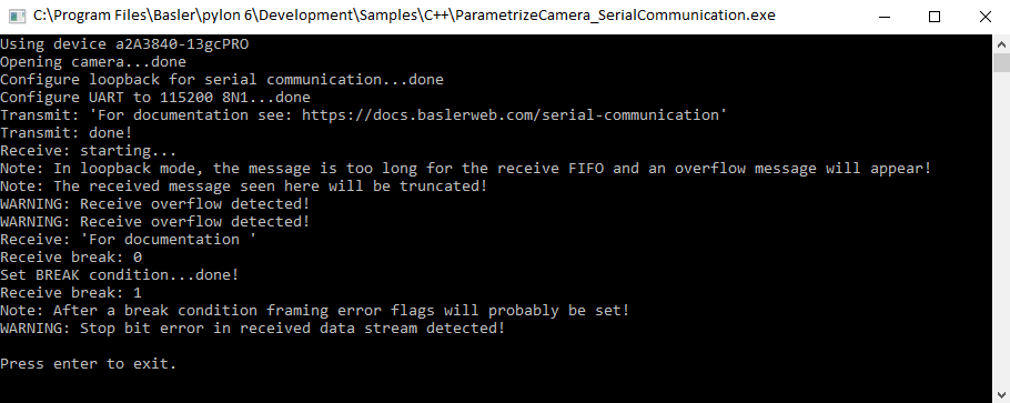
This sample demonstrates the use of the Serial Communication feature (UART) supported by ace 2 Pro cameras. This feature allows you to establish serial communication between a host and an external device through the camera's I/O lines. For more information, see the Serial Communication feature topic.
Code#
Info
You can find the sample code here.
The CBaslerUniversalInstantCamera class is used to create a camera object with the first camera found. Make sure to use an ace 2 Pro camera that supports the serial communication feature. Otherwise, an exception will be returned when trying to access and configure the camera's I/O lines.
To test the serial communication without having an external device connected to the camera, or to rule out errors caused by the external device, you can configure a loopback mode on the camera. This is done by setting the BslSerialRxSource parameter to SerialTx.
In this case, the serial input is connected to the serial output internally, so the camera receives exactly what it transmits.
To configure the serial communication between the camera and an external device, the GPIO Line 2 (SerialTx) and GPIO Line 3 (BslSerialRxSource) must be configured accordingly. Make sure not to use the opto-coupled I/O lines for UART communications.
In addition, depending on the configuration of the external device, the camera's baud rate (BslSerialBaudRate), the number of data bits (BslSerialNumberOfDataBits), the number of stop bits (BslSerialNumberOfStopBits), and the kind of parity check (BslSerialParity) must be configured.
After the serial communication has been configured, you can send data to the external device, via the SerialTransmit() function, and receive data from it, via the SerialReceive() function.
Applicable Interfaces#
- GigE Vision
- USB3 Vision
ParametrizeCamera_Shading#
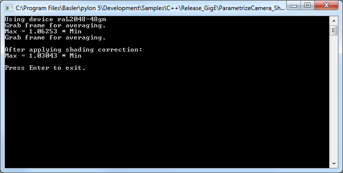
This sample demonstrates how to calculate and upload gain shading sets to Basler racer and Basler runner line scan GigE Vision cameras.
Code#
Info
You can find the sample code here.
The CDeviceInfo class is used to look for cameras with a specific interface, e.g., GigE Vision only (BaslerGigEDeviceClass).
The CBaslerUniversalInstantCamera class is used to create a camera object with the first GigE camera found.
The CAcquireSingleFrameConfiguration class is used to register the standard event handler for configuring single frame acquisition. This overrides the default configuration as all event handlers are removed by setting the registration mode to RegistrationMode_ReplaceAll.
CreateShadingData() assumes that the conditions for exposure (illumination, exposure time, etc.) have been set up to deliver images of uniform intensity (gray value), but that the acquired images are not uniform. The gain shading data is calculated so that the observed non-uniformity will be compensated when the data is applied. The data is saved in a local file.
UploadFile() transfers the calculated gain shading data from the local file to the camera.
CheckShadingData() tests to what extent the non-uniformity has been compensated.
Applicable Interfaces#
- GigE Vision
ParametrizeCamera_Shading_Racer2#
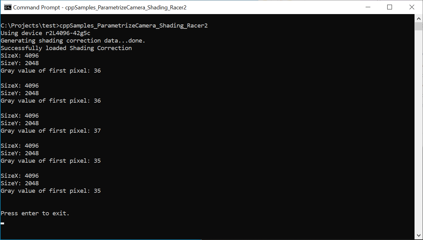
This sample demonstrates how to create and use shading sets with Basler racer 2 line scan cameras as this has become much easier compared to racer cameras.
Attention
Executing this sample will overwrite all current settings in user shading set 1.
Code#
Info
You can find the sample code here.
The CBaslerUniversalInstantCamera class is used to create a camera object with the first camera found. This object is then used to ensure that it is a line scan camera that supports the racer 2 type of shading correction.
The BslShadingCorrectionSelector, BslShadingCorrectionMode, and BslShadingCorrectionSetIndex camera parameters are used to select the type of shading correction and the storage location of the correction data.
Once image capture has been started, the BslShadingCorrectionSetCreate camera parameter can be used to start the automatic generation of the shading data.
The BslShadingCorrectionSetCreateStatus and BslShadingCorrectionSetStatus parameters can then be used to check whether the generation of the data has been completed and was successful.
Once the shading data has been generated, it is used immediately to correct subsequent image captures.
Applicable Interfaces#
- GigE Vision
- CXP
ParametrizeCamera_UserSets#
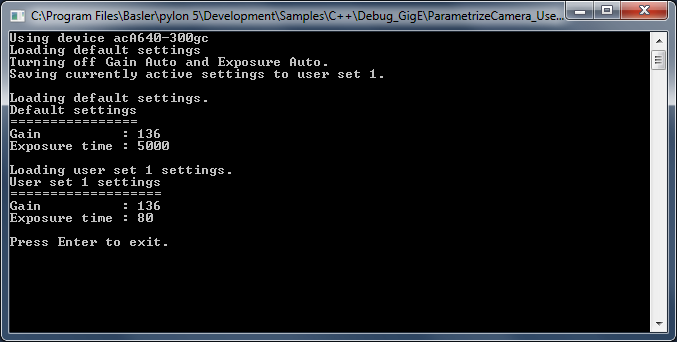
This sample demonstrates how to use user configuration sets (user sets) and how to configure the camera to start up with the user-defined settings of user set 1.
You can also use the pylon Viewer to configure your camera and store custom settings in a user set of your choice.
Info
Different camera families implement different versions of the Standard Feature Naming Convention (SFNC). That's why the name and the type of the parameters used can be different.
Attention
Executing this sample will overwrite all current settings in user set 1.
Code#
Info
You can find the sample code here.
The CBaslerUniversalInstantCamera class is used to create a camera object with the first camera device found independent of its interface.
The camera parameters UserSetSelector, UserSetLoad, UserSetSave, and UserSetDefaultSelector are used to demonstrate the use of user configuration sets (user sets) and how to configure the camera to start up with user-defined settings.
Applicable Interfaces#
- GigE Vision
- USB3 Vision
- Camera Link
- CXP
Utility_ChangeApplet#
This sample shows two different methods for changing an applet on a Basler CXP frame grabber. An applet reconfigures the on-board logic, e.g., switching from a monochrome stream to a Bayer-demosaicing pipeline. It only becomes active after all devices using the applet have been closed and the hardware has been enumerated again.
Configuring the Camera#
- Open the CXP interface (
BaslerGenTlCxpDeviceClass) withCUniversalInstantInterface. - Access the interface node map and read the current value of
InterfaceAppletandInterfaceAppletStatus. - List available applets and pick the first one that differs from the current setting.
- Method 1 - Refresh device list:
- Close all devices.
- Call
EnumerateDevices. - Check that
InterfaceAppletStatusreports Loaded.
- Method 2 - Restart pylon runtime:
- Terminate pylon completely (
PylonTerminate()). - Re‑initialize pylon (
PylonInitialize()). - Reopen the interface, and verify the status.
- Terminate pylon completely (
- Method 1 - Refresh device list:
Both approaches end with the desired applet loaded and ready for use.
Key Transport Layer Parameters#
| Node | Purpose |
|---|---|
| InterfaceApplet | Sets the desired applet. |
| InterfaceAppletStatus | Reports the current load state, e.g., Loaded, Loading, Error. |
Applicable Interfaces#
- CXP
Utility_FFC#
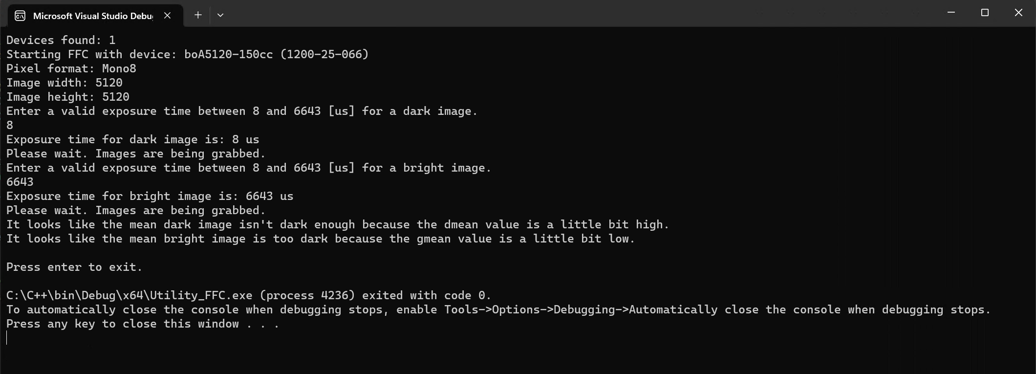
This sample demonstrates how to configure and use the Flat-Field Correction (FFC) feature of Basler boost V CXP-12 cameras.
Flat-field correction is used to eliminate differences in the brightness of pixels. The process consists of two steps:
- In step 1, sequences of dark field and bright field (flat field) images are acquired to detect dark signal non-uniformities (DSNU), e.g., dark current noise, and photo response non-uniformities (PRNU) respectively.
- In step 2, correction values are determined and uploaded to the camera.
For more information, see the Flat-Field Correction feature topic.
Code#
The findBoostCam() function is used to filter out any cameras that don't support the Flat-Field Correction feature.
In the main() method, the camera's Width, Height, PixelFormat, and ExposureTime parameters are configured for optimum results.
The processImages() function is used to grab a specified number of images. The gray values of all pixels in these images are then added up and divided by the number of images to create an average image. Next, the average gray value of each column of the average image is calculated. This forms the basis for calculating the DSNU and PRNU correction values. This is done for both dark field and flat field images.
Once the correction values for DSNU and PRNU have been calculated, they are transferred to the camera's flash memory. With this, the camera can perform flat-field correction in real-time by itself.
Applicable Interfaces#
- CXP (boost V)
Utility_GrabAvi#
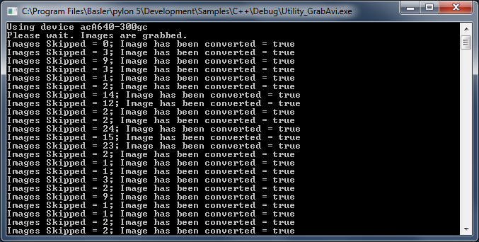
This sample demonstrates how to create a video file in Audio Video Interleave (AVI) format on Windows operating systems only.
Info
AVI is best for recording high-quality lossless videos because it allows you to record without compression. The disadvantage is that the file size is limited to 2 GB. Once that threshold is reached, the recording stops and an error message is displayed.
Code#
Info
You can find the sample code here.
The CAviWriter class is used to create an AVI writer object. The writer object takes the following arguments: file name, playback frame rate, pixel output format, width and height of the image, vertical orientation of the image data, and compression options (optional).
StartGrabbing() demonstrates how to start the grabbing by applying the GrabStrategy_LatestImages grab strategy. Using this strategy is recommended when images have to be recorded.
The CInstantCamera class is used to create an Instant Camera object with the first camera device found.
The CGrabResultPtr class is used to initialize a smart pointer that will receive the grab result data. It controls the reuse and lifetime of the referenced grab result. When all smart pointers referencing a grab result go out of scope, the referenced grab result is reused or destroyed. The grab result is still valid after the camera object it originated from has been destroyed.
The DisplayImage class is used to display the grabbed images.
Add() converts the grabbed image to the correct format, if required, and adds it to the AVI file.
Applicable Interfaces#
- GigE Vision
- USB3 Vision
- CXP
Utility_GrabVideo#
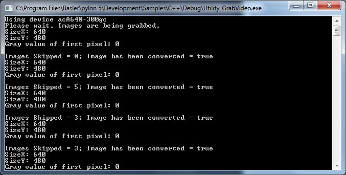
This sample demonstrates how to create a video file in MP4 format. It is presumed that the pylon Supplementary Package for MPEG-4 is already installed.
Info
There are no file size restrictions when recording MP4 videos. However, the MP4 format always compresses data to a certain extent, which results in loss of detail.
Code#
Info
You can find the sample code here.
The CVideoWriter class is used to create a video writer object. Before opening the video writer object, it is initialized with the current parameter values of the ROI width and height, the pixel output format, the playback frame rate, and the quality of compression.
StartGrabbing() demonstrates how to start the grabbing by applying the GrabStrategy_LatestImages grab strategy. Using this strategy is recommended when images have to be recorded.
The CInstantCamera class is used to create an Instant Camera object with the first camera device found.
The CGrabResultPtr class is used to initialize a smart pointer that will receive the grab result data. It controls the reuse and lifetime of the referenced grab result. When all smart pointers referencing a grab result go out of scope, the referenced grab result is reused or destroyed. The grab result is still valid after the camera object it originated from has been destroyed.
The DisplayImage class is used to display the grabbed images.
Add() converts the grabbed image to the correct format, if required, and adds it to the video file.
Applicable Interfaces#
- GigE Vision
- USB3 Vision
- CXP
Utility_Image#
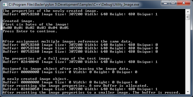
This sample demonstrates how to use the pylon image classes CPylonImage and CPylonBitmapImage.
CPylonImage supports handling image buffers of the various existing pixel types.
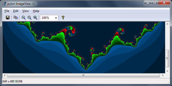
CPylonBitmapImage can be used to easily create Windows bitmaps for displaying images. In additional, there are two image class-related interfaces in pylon (IImage and IReusableImage).
IImage can be used to access image properties and the image buffer.
The IReusableImage interface extends the IImage interface to be able to reuse the resources of the image to represent a different image.
Both CPylonImage and CPylonBitmapImage implement the IReusableImage interface.
The CGrabResultPtr grab result class provides a cast operator to the IImage interface. This makes using the grab result together with the image classes easier.
Code#
Info
You can find the sample code here.
The CPylonImage class describes an image. It takes care of the following:
- Automatically manages size and lifetime of the image.
- Allows taking over a grab result to prevent its reuse as long as required.
- Allows connecting user buffers or buffers provided by third-party software packages.
- Provides methods for loading and saving an image in different file formats.
- Serves as the main target format for the
CImageFormatConverterclass. - Makes working with planar images easier.
- Makes extracting AOIs easier, e.g., for thumbnail images of defects.
The CPylonBitmapImage class can be used to easily create Windows bitmaps for displaying images. It takes care of the following:
- Automatically handles the bitmap creation and lifetime.
- Provides methods for loading and saving an image in different file formats.
- Serves as target format for the
CImageFormatConverterclass.
The bitmap image class provides a cast operator for HBitmap. The cast operator can be used for instance to provide the handle to Windows API functions.
The CImageFormatConverter class creates new images by converting a source image to another format.
The CInstantCamera class is used to create an Instant Camera object with the first camera device found.
The CGrabResultPtr class is used to initialize a smart pointer that will receive the grab result data. It controls the reuse and lifetime of the referenced grab result. When all smart pointers referencing a grab result go out of scope, the referenced grab result is reused or destroyed. The grab result is still valid after the camera object it originated from has been destroyed.
The DisplayImage class is used to display the grabbed images.
Applicable Interfaces#
- GigE Vision
- USB3 Vision
- CXP
Utility_ImageDecompressor#
This sample illustrates how to enable and use the Basler Compression Beyond feature in Basler ace 2 GigE and Basler ace 2 USB 3.0 cameras.
This sample also demonstrates how to decompress the images using the CImageDecompressor class.
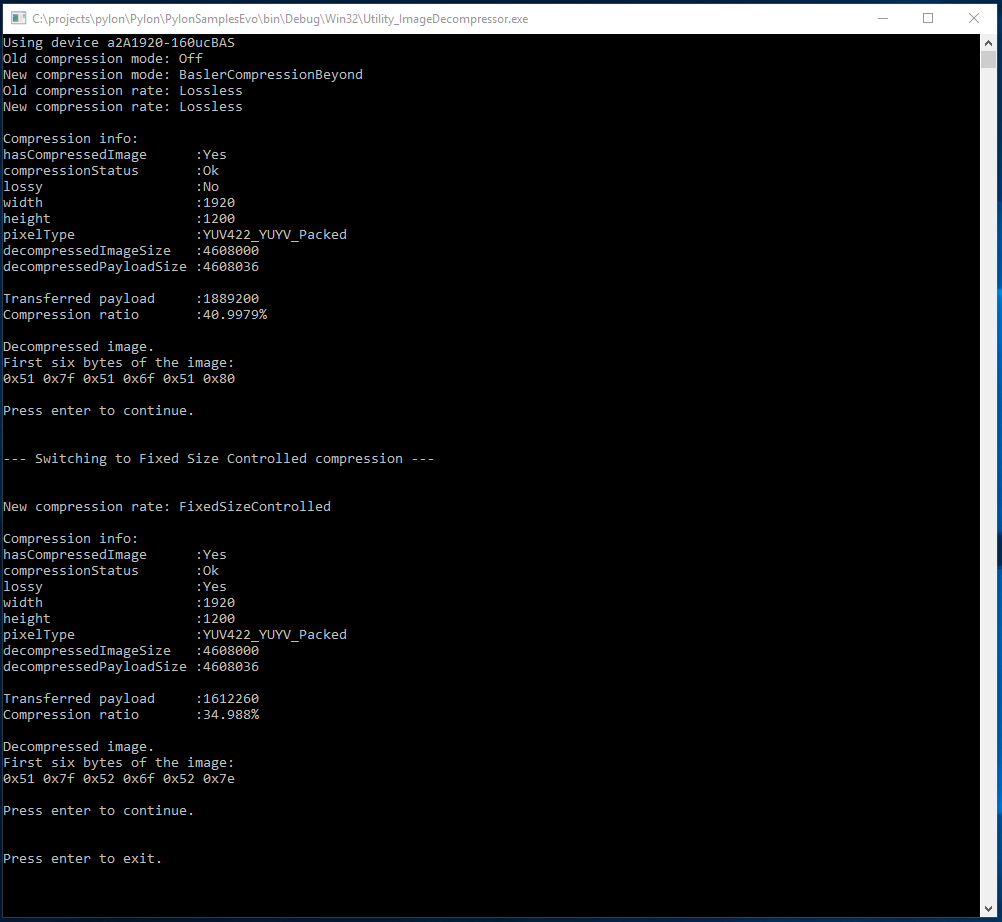
Code#
Info
You can find the sample code here.
The CInstantCamera class is used to create an Instant Camera object with the first camera device found.
The CGrabResultPtr class is used to initialize a smart pointer that will receive the grab result data. It controls the reuse and lifetime of the referenced grab result. When all smart pointers referencing a grab result go out of scope, the referenced grab result is reused or destroyed. The grab result is still valid after the camera object it originated from has been destroyed.
The CImageDecompressor class is used to decompress grabbed images. In this sample, compression and decompression are demonstrated, using lossless and lossy algorithms.
The CPylonImage class is used to create a decompressed target image. The target image is displayed in an image window.
Applicable Interfaces#
- GigE Vision
- USB3 Vision
Utility_ImageFormatConverter#
This sample demonstrates how to use the CImageFormatConverter class. The image format converter accepts all image formats produced by Basler camera devices. It can convert these to a number of output formats.
The conversion can be controlled by several parameters. For more information, see the converter class documentation.
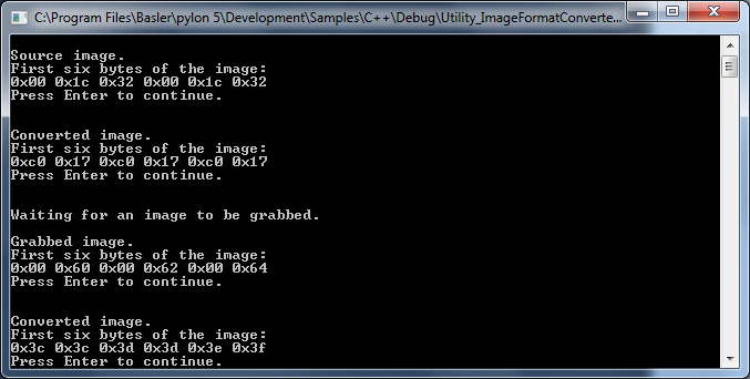
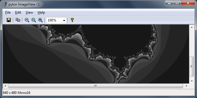
Code#
Info
You can find the sample code here.
The CImageFormatConverter class creates new images by converting a source image to another format.
The CPylonImage class describes an image. It takes care of the following:
- Automatically manages size and lifetime of the image.
- Allows taking over a grab result to prevent its reuse as long as required.
- Allows connecting user buffers or buffers provided by third-party software packages.
- Provides methods for loading and saving an image in different file formats.
- Serves as the main target format for the
CImageFormatConverterclass. - Makes working with planar images easier.
- Makes extracting image ROIs easier, e.g., for thumbnail images of defects.
The CInstantCamera class is used to create an Instant Camera object with the first camera device found.
The CGrabResultPtr class is used to initialize a smart pointer that will receive the grab result data. It controls the reuse and lifetime of the referenced grab result. When all smart pointers referencing a grab result go out of scope, the referenced grab result is reused or destroyed. The grab result is still valid after the camera object it originated from has been destroyed.
The DisplayImage class is used to display the grabbed images.
Applicable Interfaces#
- GigE Vision
- USB3 Vision
- CXP
Utility_ImageLoadAndSave#
This sample demonstrates how to load and save images.
The CImagePersistence class provides functions for loading and saving images. It uses the image class-related pylon interfaces IImage and IReusableImage.
IImage can be used to access image properties and the image buffer. Therefore, it is used when saving images. In addition to that, images can also be saved by passing an image buffer and the corresponding properties.
The IReusableImage interface extends the IImage interface to be able to reuse the resources of the image to represent a different image. The IReusableImage interface is used when loading images.
The CPylonImage and CPylonBitmapImage image classes implement the IReusableImage interface. These classes can therefore be used as targets for loading images.
The grab result smart pointer classes provide a cast operator to the IImage interface. This makes it possible to pass a grab result directly to the function that saves images to disk.
Code#
Info
You can find the sample code here.
The CImagePersistence class demonstrates how images can be loaded or saved. It can be used to check whether the image can be saved without prior conversion. Supported image file formats are TIFF, BMP, JPEG, and PNG.
The CInstantCamera class is used to create an Instant Camera object with the first camera device found.
The CGrabResultPtr class is used to initialize a smart pointer that will receive the grab result data. It controls the reuse and lifetime of the referenced grab result. When all smart pointers referencing a grab result go out of scope, the referenced grab result is reused or destroyed. The grab result is still valid after the camera object it originated from has been destroyed.
The CPylonImage class describes an image. It takes care of the following:
- Automatically manages size and lifetime of the image.
- Allows taking over a grab result to prevent its reuse as long as required.
- Allows connecting user buffers or buffers provided by third-party software packages.
- Provides methods for loading and saving an image in different file formats.
- Serves as the main target format for the
CImageFormatConverterclass. - Makes working with planar images easier.
- Makes extracting AOIs easier, e.g., for thumbnail images of defects.
Applicable Interfaces#
- GigE Vision
- USB3 Vision
- CXP
Utility_InstantInterface#
This sample illustrates how to use the CInstantInterface class to access parameters of the interface using the Basler CXP-12 interface card. The sample shows how to access the Power-over-CoaXPress settings and monitor the power usage.
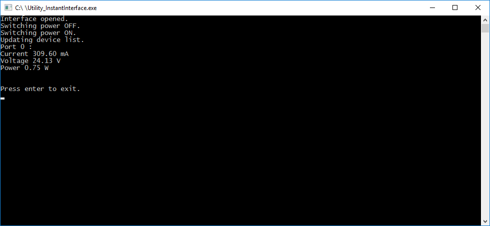
Code#
Info
You can find the sample code here.
The CInterfaceInfo class is used for storing information about an interface object provided by a specific transport layer, e.g., BaslerGenTlCxpDeviceClass.
The CUniversalInstantInterface class is used to open the first interface on the CoaXPress interface card and access its parameters. In this sample, the Power-over-CoaXPress parameter CxpPoCxpStatus is enabled/disabled. In addition, the current, voltage, and power consumption information is displayed.
Applicable Interfaces#
- CXP
Utility_IpConfig#
This sample demonstrates how to configure the IP address of a GigE Vision camera. The functionalities described in this sample are similar to those used in the pylon IP Configurator.
In addition, this sample can be used to automatically and programmatically configure multiple GigE Vision cameras. As the sample accepts command line arguments, it can be directly executed, e.g., from a batch script file.
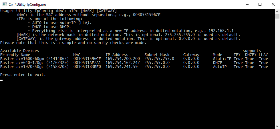
Code#
Info
You can find the sample code here.
The CTlFactory class is used to create a GigE transport layer. The GigE transport layer is required to discover all GigE Vision cameras independent of their current IP address configuration. For that purpose, the EnumerateAllDevices() function is used.
To set a new IP address of a GigE Vision camera, the BroadcastIpConfiguration() function is used.
Applicable Interfaces#
- GigE Vision
C Samples#
ActionCommands#
This sample illustrates how to grab images and trigger multiple cameras using a GigE Vision action command.
At least two connected GigE cameras are required for this sample.
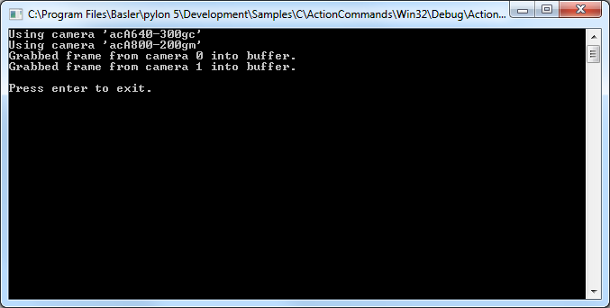
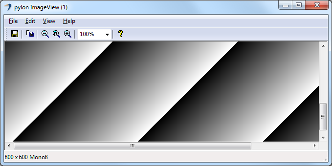
Code#
Info
You can find the sample code here.
Before using any pylon methods, the pylon runtime is initialized by calling PylonInitialize().
Then, PylonEnumerateDevices() is called to enumerate all attached camera devices.
Before using a camera device, it must be opened by calling PylonDeviceOpen(). This allows us to set parameters and grab images.
This sample works only for cameras supporting GigE Vision action commands. This is checked by calling PylonDeviceFeatureIsAvailable() and passing the device handle and the camera parameter "ActionControl" as arguments. Cameras with action command support are then configured accordingly, i.e., the parameters ActionSelector, ActionDeviceKey, ActionGroupKey, ActionGroupMask, TriggerSelector, TriggerMode, and TriggerSource are set.
If the cameras are connected to a switch, Basler recommends setting the Inter-Packet Delay (GevSCPD) and the Frame Transmission Delay (GevSCFTD) so that the switch can properly line up packets.
Images are grabbed using a stream grabber. For each camera device, a stream grabber is created by calling PylonDeviceGetStreamGrabber() and passing the device handle and the stream grabber handle as arguments. A handle for the stream grabber's wait object is retrieved within PylonStreamGrabberGetWaitObject(). The wait object allows waiting for buffers to be filled with grabbed data.
We must also tell the stream grabber the number and size of the buffers we are using. This is done with PylonStreamGrabberSetMaxNumBuffer() and PylonStreamGrabberSetMaxBufferSize(). By calling PylonStreamGrabberPrepareGrab(), we allocate the resources required for grabbing. After this, critical parameters that impact the payload size must not be changed until PylonStreamGrabberFinishGrab() is called.
Before using the buffers for grabbing, they must be registered and queued into the stream grabber's input queue. This is done with PylonStreamGrabberRegisterBuffer() and PylonStreamGrabberQueueBuffer().
To enable image acquisition, PylonDeviceExecuteCommandFeature() is called with the device handle and the AcqusitionStart camera parameter as arguments. After that, the cameras are triggered using PylonGigEIssueActionCommand().
In PylonWaitObjectsWaitForAny(), we wait for the next buffer to be filled with a timeout of 5000 ms. The grabbed image is retrieved by calling PylonStreamGrabberRetrieveResult().
With PylonImageWindowDisplayImageGrabResult(), images are displayed in an image window.
When image acquisition is stopped, we must perform a cleanup for all cameras, i.e., all wait objects must be removed, all allocated buffer memory must be released, and the stream grabber as well as the camera device handles must be closed and destroyed.
Finally, we shut down the pylon runtime system by calling PylonTerminate(). No pylon functions should be called after calling PylonTerminate().
Applicable Interfaces#
- GigE Vision
Chunks#
Basler cameras supporting the Data Chunk feature can generate supplementary image data, e.g., frame count, time stamp, or CRC checksums, and append it to each acquired image.
This sample illustrates how to enable the Data Chunk feature, how to grab images, and how to process the appended data. When the camera is in chunk mode, it transfers data blocks partitioned into chunks. The first chunk is always the image data. If one or more data chunks are enabled, these chunks are transmitted as chunk 2, 3, and so on.
This sample also demonstrates how to use software triggers. Two buffers are used. Once a buffer is filled, the acquisition of the next frame is triggered before processing the received buffer. This approach allows acquiring images while the previous image is still being processed.
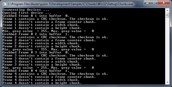
Code#
Info
You can find the sample code here.
Before using any pylon methods, the pylon runtime is initialized by calling PylonInitialize().
Then, PylonEnumerateDevices() is called to enumerate all attached camera devices.
Before using a camera device, it must be opened by calling PylonDeviceOpen(). This allows us to set parameters and grab images.
As the camera will be triggered by software trigger, the TriggerMode and TriggerSource camera parameters are configured accordingly.
When using software triggering, the Continuous frame mode should be used. This is done by passing the device handle and the camera parameters "AcquisitionMode" and "Continuous" as arguments to PylonDeviceFeatureFromString().
Before enabling individual chunks, the chunk mode must be activated. In this sample, the frame counter and the CRC checksum data chunks are enabled as well.
The data block containing the image chunk and the other chunks has a self-descriptive layout. A chunk parser is used to extract the appended chunk data from the grabbed image frame. A chunk parser is created with PylonDeviceCreateChunkParser() by passing the device and the chunk parser handles as arguments.
Images are grabbed using a stream grabber. For each camera device, a stream grabber is created by calling PylonDeviceGetStreamGrabber() and passing the device handle and the stream grabber handle as arguments. A handle for the stream grabber's wait object is retrieved within PylonStreamGrabberGetWaitObject(). The wait object allows waiting for buffers to be filled with grabbed data.
We must also tell the stream grabber the number and size of the buffers we are using. This is done with PylonStreamGrabberSetMaxNumBuffer() and PylonStreamGrabberSetMaxBufferSize(). By calling PylonStreamGrabberPrepareGrab() we allocate the resources required for grabbing. After this, critical parameters that impact the payload size must not be changed until PylonStreamGrabberFinishGrab() is called.
Before using the buffers for grabbing, they must be registered and queued into the stream grabber's input queue. This is done with PylonStreamGrabberRegisterBuffer() and PylonStreamGrabberQueueBuffer().
To enable image acquisition, PylonDeviceExecuteCommandFeature() is called with the device handle and the AcqusitionStart camera parameter as arguments.
Because the trigger mode is enabled, issuing the acquisition start command itself will not trigger any image acquisitions. Issuing the start command simply prepares the camera to acquire images. Once the camera is prepared it will acquire one image for every trigger it receives.
Software triggers are issued by calling PylonDeviceExecuteCommandFeature() while passing the device handle and the "TriggerSoftware" camera parameter as arguments.
In PylonWaitObjectsWait(), we wait for the next buffer to be filled with a timeout of 1000 ms. The grabbed image is retrieved by calling PylonStreamGrabberRetrieveResult().
If the image was grabbed successfully, we let the chunk parser extract the chunk data by calling PylonChunkParserAttachBuffer().
After image processing is completed and before re-queueing the buffer, we detach it from the chunk parser by calling PylonChunkParserDetachBuffer(). Then, we re-queue the buffer to be filled with image data by calling PylonStreamGrabberQueueBuffer().
When image acquisition is stopped, we must perform a cleanup for all cameras, i.e., all wait objects must be removed, all allocated buffer memory must be released, and the stream grabber as well as the camera device handles must be closed and destroyed.
Finally, we shut down the pylon runtime system by calling PylonTerminate(). No pylon functions should be called after calling PylonTerminate().
Applicable Interfaces#
- GigE Vision
- USB3 Vision
Events#
Basler GigE Vision and USB3 Vision cameras can send event messages. For example, when a sensor exposure has finished, the camera can send an Exposure End event to the computer. The event can be received by the computer before the image data for the finished exposure has been completely transferred. This sample illustrates how to retrieve and process event messages.
Receiving events is similar to grabbing images. An event grabber provides a wait object that is notified when an event message is available. When an event message is available, it can be retrieved from the event grabber. In contrast to grabbing images, you don't need to provide memory buffers to receive events. The memory buffers are organized by the event grabber itself.
The specific layout of event messages depends on the event type and the camera type. The event message layout is described in the camera's GenICam XML description file. From the file, a GenApi node map is created. This means that the information carried by the event messages is exposed as nodes in the node map and can be accessed like standard camera parameters.
You can register callback functions that are fired when a parameter has been changed. To be informed that a received event message contains a specific event, you must register a callback for the parameters associated with the event.
These mechanisms are demonstrated with the Exposure End event. The event carries the following information:
- ExposureEndEventFrameID: Number of the image that has been exposed.
- ExposureEndEventTimestamp: Time when the event was generated.
- ExposureEndEventStreamChannelIndex: Number of the image data stream used to transfer the image. On Basler cameras, this parameter is always set to 0.
A callback for the ExposureEndEventFrameID will be registered as an indicator for the arrival of an end-of-exposure event.
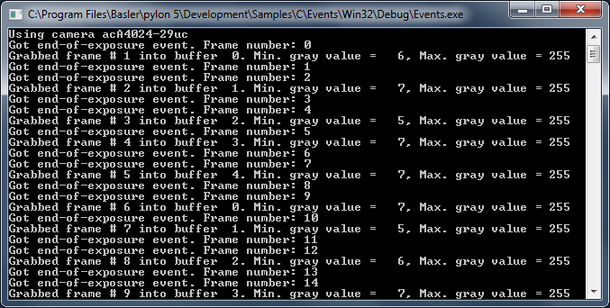
Code#
Info
You can find the sample code here.
Before using any pylon methods, the pylon runtime is initialized by calling PylonInitialize().
Then, PylonEnumerateDevices() is called to enumerate all attached camera devices.
Before using a camera device, it must be opened by calling PylonDeviceOpen(). This allows us to set parameters and grab images.
In this sample, we will use the Continuous acquisition mode, i.e., the camera delivers images continuously. We do this by calling PylonDeviceFeatureFromString() while passing the device handle and the camera parameters "AcquisitionMode" and "Continuous" as arguments.
To make use of camera events, we enable camera event reporting and select the Exposure End event.
To handle events, we create and prepare an event grabber by calling PylonDeviceGetEventGrabber() while passing the device and event grabber handles as arguments. We tell the grabber how many buffers to use by calling PylonEventGrabberSetNumBuffers().
In PylonEventGrabberGetWaitObject(), we retrieve the wait object that is associated with the event grabber. The event will be notified when an event message has been received.
To extract the event data from an event message, an event adapter is used. We create it by calling PylonDeviceCreateEventAdapter().
We then register a callback function for the ExposureEndEventFrameID parameter by getting it from the device node map and calling GenApiNodeRegisterCallback().
We create a container (PylonWaitObjectsCreate) and put the wait objects for image and event data into it (PylonWaitObjectsAddMany).
Images are grabbed using a stream grabber. For each camera device, a stream grabber is created by calling PylonDeviceGetStreamGrabber() and passing the device handle and the stream grabber handle as arguments. A handle for the stream grabber's wait object is retrieved with PylonStreamGrabberGetWaitObject(). The wait object allows waiting for buffers to be filled with grabbed data.
We must also tell the stream grabber the number and size of the buffers we are using. This is done with PylonStreamGrabberSetMaxNumBuffer() and PylonStreamGrabberSetMaxBufferSize(). By calling PylonStreamGrabberPrepareGrab(), we allocate the resources required for grabbing. After this, critical parameters that impact the payload size must not be changed until PylonStreamGrabberFinishGrab() is called.
Before using the buffers for grabbing, they must be registered and queued into the stream grabber's input queue. This is done with PylonStreamGrabberRegisterBuffer() and PylonStreamGrabberQueueBuffer().
To enable image acquisition, PylonDeviceExecuteCommandFeature() is called with the device handle and the AcquisitionStart camera parameter as arguments.
In PylonWaitObjectsWaitForAny(), we wait for either an image buffer grabbed or an event received with a timeout of 1000 ms.
Grabbed images are retrieved by calling PylonStreamGrabberRetrieveResult().
Grabbed events are retrieved by calling PylonEventGrabberRetrieveEvent().
Once finished with the processing, we re-queue the buffer to be filled again by calling PylonStreamGrabberQueueBuffer().
When image acquisition is stopped, we must perform a cleanup for all cameras, i.e., all wait objects must be removed, all allocated buffer memory must be released, and the stream grabber as well as the camera device handles must be closed and destroyed.
Finally, we shut down the pylon runtime system by calling PylonTerminate(). No pylon functions should be called after calling PylonTerminate().
Applicable Interfaces#
- GigE Vision
- USB3 Vision
GenApiParam#
This sample illustrates how to access the different camera parameter types. It uses the low-level functions provided by GenApiC instead of those provided by pylonC.
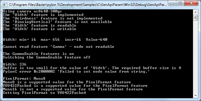
Code#
Info
You can find the sample code here.
Before using any pylon methods, the pylon runtime is initialized by calling PylonInitialize().
Then, PylonEnumerateDevices() is called to enumerate all attached camera devices.
Before using a camera device, it must be opened. Open it by calling PylonDeviceOpen() for setting parameters afterwards.
The following helper functions are used:
demonstrateAccessibilityCheck(): Demonstrates how to check the accessibility of a camera feature, e.g., whether the camera feature "BinningVertical" is implemented and available for the current camera.demonstrateIntFeature(): Demonstrates how to handle integer camera parameters, e.g., the camera feature "Width".demonstrateFloatFeature(): Demonstrates how to handle floating point camera parameters, e.g., the camera feature "Gamma".demonstrateBooleanFeature(): Demonstrates how to handle boolean camera parameters, e.g., the camera feature "GammaEnable".demonstrateFromStringToString(): Demonstrates how to read or set camera features as a string. Regardless of the parameter's type, any parameter value can be retrieved as a string. In addition, each parameter can be set by passing in a string. This function illustrates how to set and get the integer parameter "Width" as string.demonstrateEnumFeature(): Demonstrates how to handle enumeration camera parameters, e.g., the camera feature "PixelFormat".demonstrateEnumIteration(): Demonstrates how to iterate enumeration entries, e.g., the enumeration entries of the camera feature "PixelFormat".demonstrateCommandFeature(): Demonstrates how to execute commands, e.g., load the camera factory settings by executing the "UserSetLoad" command.demonstrateCategory(): Demonstrates category node. The function traverses the feature tree, displaying all categories and all features.
Finally, a cleanup is done, e.g., the pylon device is closed and released. The pylon runtime system is shut down by calling PylonTerminate(). No pylon functions should be called after calling PylonTerminate().
Applicable Interfaces#
- GigE Vision
- USB3 Vision
- Camera Link
- CXP
GrabTwoCameras#
This sample illustrates how to grab images and process images using multiple cameras simultaneously.
The sample uses a pool of buffers that are passed to a stream grabber to be filled with image data. Once a buffer is filled and ready for processing, the buffer is retrieved from the stream grabber, processed, and passed back to the stream grabber to be filled again. Buffers retrieved from the stream grabber are not overwritten as long as they are not passed back to the stream grabber.
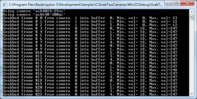
Code#
Info
You can find the sample code here.
Before using any pylon methods, the pylon runtime is initialized by calling PylonInitialize().
Then, PylonEnumerateDevices() is called to enumerate all attached camera devices.
Before using a camera device, it must be opened by calling PylonDeviceOpen(). This allows us to set parameters and grab images.
Images are grabbed using a stream grabber. For each camera device, a stream grabber is created by calling PylonDeviceGetStreamGrabber() and passing the device handle and the stream grabber handle as arguments. A handle for the stream grabber's wait object is retrieved within PylonStreamGrabberGetWaitObject(). The wait object allows waiting for buffers to be filled with grabbed data.
We must also tell the stream grabber the number and size of the buffers we are using. This is done with PylonStreamGrabberSetMaxNumBuffer() and PylonStreamGrabberSetMaxBufferSize(). By calling PylonStreamGrabberPrepareGrab() we allocate the resources required for grabbing. After this, critical parameters that impact the payload size must not be changed until PylonStreamGrabberFinishGrab() is called.
Before using the buffers for grabbing, they must be registered and queued into the stream grabber's input queue. This is done with PylonStreamGrabberRegisterBuffer() and PylonStreamGrabberQueueBuffer().
We call PylonDeviceExecuteCommandFeature() with the device handle and the AcqusitionStart camera parameter as arguments on each camera to start the image acquisition.
In PylonWaitObjectsWaitForAny(), we wait for the next buffer to be filled with a timeout of 1000 ms. The grabbed image is retrieved by calling PylonStreamGrabberRetrieveResult().
With PylonImageWindowDisplayImageGrabResult(), images are displayed in different image windows.
Once finished with the processing, we re-queue the current grabbed buffer to be filled again by calling PylonStreamGrabberQueueBuffer().
When image acquisition is stopped, we must perform a cleanup for all cameras, i.e., all wait objects must be removed, all allocated buffer memory must be released, and the stream grabber as well as the camera device handles must be closed and destroyed.
Finally, we shut down the pylon runtime system by calling PylonTerminate(). No pylon functions should be called after calling PylonTerminate().
Applicable Interfaces#
- GigE Vision
- USB3 Vision
- CXP
ImageDecompressor#
This sample illustrates how to enable and use the Basler Compression Beyond feature in Basler ace 2 Pro GigE and Basler ace 2 Pro USB 3.0 cameras.
This sample also demonstrates how to create and configure a pylon decompressor and use it to decompress the compressed camera images.
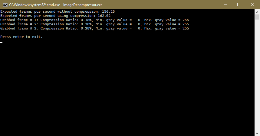
Code#
Info
You can find the sample code here.
Before using any pylon methods, the pylon runtime is initialized by calling PylonInitialize().
Then, PylonEnumerateDevices() is called to enumerate all attached camera devices.
Before using a camera device, it must be opened by calling PylonDeviceOpen(). This allows us to set parameters, e.g., to set the ImageCompressionMode parameter to On or Off.
The configureCompression() function is used either to switch off the Compression Beyond feature or to configure the camera for lossless compression. In addition, you can also enable and use lossy compression.
The image decompressor is created by passing the decompressor handle to PylonImageDecompressorCreate().
To be able to decompress image data, we have to set the compression descriptor first. This is done by calling PylonImageDecompressorSetCompressionDescriptor() while passing the decompressor handle, the buffer used to store the compression descriptor, and the size of the compression descriptor as arguments.
Image grabbing is typically done by using a stream grabber. As we grab a single image in this sample, we allocate a single image buffer (malloc) without setting up a stream grabber.
The camera is set to Single Frame acquisition mode. We grab one single frame in a loop by calling PylonDeviceGrabSingleFrame(). We wait up to 2000 ms for the image to be grabbed.
As the information about the compressed image data is transmitted as chunk data, we retrieve this information by calling PylonImageDecompressorGetCompressionInfo().
The decompression of the image data is done in PylonImageDecompressorDecompressImage(). When decompression is complete, information about the resulting frame rate, i.e., possible speed increases and the compression ratio applied, is printed in the terminal.
With PylonImageWindowDisplayImageGrabResult(), images are displayed in an image window.
At application exit, a cleanup for the camera device must be done, i.e., all allocated buffer memory must be released and the decompressor and the camera device handles must be freed and destroyed.
Applicable Interfaces#
- GigE Vision
- USB3 Vision
OverlappedGrab#
This sample illustrates how to grab and process images asynchronously, i.e., while the application is processing a buffer, the acquisition of the next buffer is done in parallel. The sample uses a pool of buffers that are passed to a stream grabber to be filled with image data. Once a buffer is filled and ready for processing, the buffer is retrieved from the stream grabber, processed, and passed back to the stream grabber to be filled again. Buffers retrieved from the stream grabber are not overwritten as long as they are not passed back to the stream grabber.
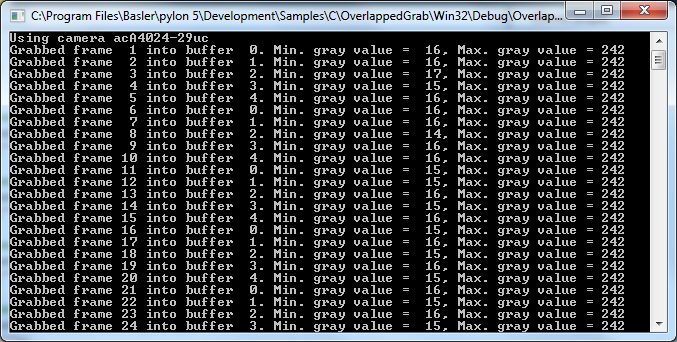
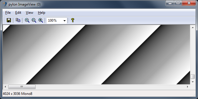
Code#
Info
You can find the sample code here.
Before using any pylon methods, the pylon runtime is initialized by calling PylonInitialize().
Then, PylonEnumerateDevices() is called to enumerate all attached camera devices.
Before using a camera device, it must be opened by calling PylonDeviceOpen(). This allows us to set parameters and grab images.
Images are grabbed using a stream grabber. For each camera device, a stream grabber is created by calling PylonDeviceGetStreamGrabber() and passing the device handle and the stream grabber handle as arguments. A handle for the stream grabber's wait object is retrieved within PylonStreamGrabberGetWaitObject(). The wait object allows waiting for buffers to be filled with grabbed data.
We must also tell the stream grabber the number and size of the buffers we are using. This is done with PylonStreamGrabberSetMaxNumBuffer() and PylonStreamGrabberSetMaxBufferSize(). By calling PylonStreamGrabberPrepareGrab() we allocate the resources required for grabbing. After this, critical parameters that impact the payload size must not be changed until PylonStreamGrabberFinishGrab() is called.
Before using the buffers for grabbing, they must be registered and queued into the stream grabber's input queue. This is done with PylonStreamGrabberRegisterBuffer() and PylonStreamGrabberQueueBuffer().
Call PylonDeviceExecuteCommandFeature() with the device handle and the AcqusitionStart camera parameter as arguments on each camera to start the image acquisition.
In PylonWaitObjectsWait() we wait for the next buffer to be filled with a timeout of 1000 ms. The grabbed image is retrieved by calling PylonStreamGrabberRetrieveResult().
With PylonImageWindowDisplayImageGrabResult(), images are displayed in an image window.
Once finished with the processing, we re-queue the current grabbed buffer to be filled again by calling PylonStreamGrabberQueueBuffer().
When image acquisition is stopped, we must perform a cleanup for all cameras, i.e., all allocated buffer memory must be released and the stream grabber as well as the camera device handles must be closed and destroyed.
Finally, we shut down the pylon runtime system by calling PylonTerminate(). No pylon functions should be called after calling PylonTerminate().
Applicable Interfaces#
- GigE Vision
- USB3 Vision
- CXP
ParametrizeCamera#
This sample illustrates how to read and write different camera parameter types.
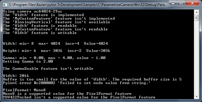
Code#
Info
You can find the sample code here.
Before using any pylon methods, the pylon runtime is initialized by calling PylonInitialize().
Then, PylonEnumerateDevices() is called to enumerate all attached camera devices.
Before using a camera device, it must be opened by calling PylonDeviceOpen(). This allows us to set parameters.
The following helper functions are used:
demonstrateAccessibilityCheck(): Demonstrates how to check the accessibility of a camera feature, e.g., whether the camera feature "BinningVertical" is implemented and available for the current camera.demonstrateIntFeature(): Demonstrates how to handle integer camera parameters, e.g., the camera feature "Width".demonstrateInt32Feature(): Demonstrates how to handle integer camera parameters, e.g., the camera feature "Height".demonstrateFloatFeature(): Demonstrates how to handle floating point camera parameters, e.g., the camera feature "Gamma".demonstrateBooleanFeature(): Demonstrates how to handle boolean camera parameters, e.g., the camera feature "GammaEnable".demonstrateFromStringToString(): Demonstrates how to read or set camera features as a string. Regardless of the parameter's type, any parameter value can be retrieved as a string. In addition, each parameter can be set by passing in a string. This function illustrates how to set and get the integer parameter "Width" as string.demonstrateEnumFeature(): Demonstrates how to handle enumeration camera parameters, e.g., the camera feature "PixelFormat".demonstrateCommandFeature(): Demonstrates how to execute commands, e.g., load the camera factory settings by executing the "UserSetLoad" command.
Finally, a cleanup is done, e.g., the pylon device is closed and released. The pylon runtime system is shut down by calling PylonTerminate(). No pylon functions should be called after calling PylonTerminate().
Applicable Interfaces#
- GigE Vision
- USB3 Vision
- Camera Link
- CXP
SimpleGrab#
This sample illustrates how to use the PylonDeviceGrabSingleFrame() convenience method for grabbing images in a loop. PylonDeviceGrabSingleFrame() grabs one single frame in single frame mode.
Grabbing in Single Frame acquisition mode is the easiest way to grab images.
Info
In Single Frame mode, the maximum frame rate of the camera can't be achieved. The maximum frame rate can be achieved by setting the camera to the Continuous frame acquisition mode and by grabbing in overlapped mode, i.e., image acquisition begins while the camera is still processing the previous image. This is illustrated in the OverlappedGrab sample program.
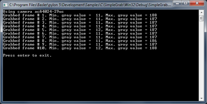
Code#
Info
You can find the sample code here.
Before using any pylon methods, the pylon runtime is initialized by calling PylonInitialize().
Then, PylonEnumerateDevices() is called to enumerate all attached camera devices.
Before using a camera device, it must be opened by calling PylonDeviceOpen(). This allows us to set parameters and grab images.
Image grabbing is typically done by using a stream grabber. As we grab a single image in this sample, we allocate a single image buffer (malloc) without setting up a stream grabber.
The camera is set to Single Frame acquisition mode. We grab one single frame in a loop by calling PylonDeviceGrabSingleFrame(). We wait up to 500 ms for the image to be grabbed.
With PylonImageWindowDisplayImageGrabResult(), images are displayed in an image window.
When the image acquisition is stopped, a cleanup for the camera device must be done, i.e., all allocated buffer memory must be released and the camera device handles must be closed and destroyed.
Finally, we shut down the pylon runtime system by calling PylonTerminate(). No pylon functions should be called after calling PylonTerminate().
Applicable Interfaces#
- GigE Vision
- USB3 Vision
- CXP
SurpriseRemoval#
This sample program demonstrates how to be informed about a sudden removal of a device.
Info
If you build this sample in debug mode and run it using a GigE camera device, pylon will set the heartbeat timeout to 5 minutes. This is done to allow debugging and single-stepping without losing the camera connection due to missing heartbeats. However, with this setting, it would take 5 minutes for the application to notice that a GigE device has been disconnected. As a workaround, the heartbeat timeout is set to 1000 ms.
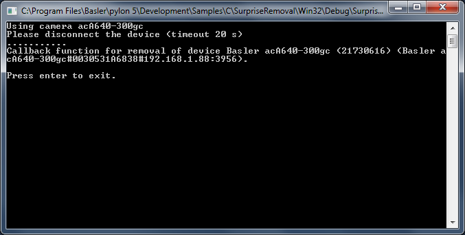
Code#
Info
You can find the sample code here.
Before using any pylon methods, the pylon runtime is initialized by calling PylonInitialize().
Then, PylonEnumerateDevices() is called to enumerate all attached camera devices.
Before using a camera device, it must be opened by calling PylonDeviceOpen(). This allows us to set parameters and grab images.
In PylonDeviceRegisterRemovalCallback(), we register the removalCallbackFunction() callback function. This function will be called when the opened device has been removed.
The setHeartbeatTimeout() function is used to adjust the heartbeat timeout. For GigE cameras, the application periodically sends heartbeat signals to the camera to keep the connection to the camera alive. If the camera doesn't receive heartbeat signals within the time period specified by the heartbeat timeout counter, the camera resets the connection. When the application is stopped by the debugger, the application cannot create the heartbeat signals. For that reason, the pylon runtime extends the heartbeat timeout when debugging to 5 minutes. For GigE cameras, we will set the heartbeat timeout to a shorter period before testing the callbacks.
The heartbeat mechanism is also used for detection of device removal. When the pylon runtime doesn't receive acknowledges for the heartbeat signal, it is assumed that the device has been removed. A removal callback will be fired in that case. By decreasing the heartbeat timeout, the surprise removal will be noticed earlier.
When we exit the application, a cleanup for the camera device must be done, i.e., the removal callback must be deregistered and the camera device handle must be closed and destroyed.
Finally, we shut down the pylon runtime system by calling PylonTerminate(). No pylon functions should be called after calling PylonTerminate().
Applicable Interfaces#
- GigE Vision
- USB3 Vision
- Camera Link
.NET Samples#
DeviceRemovalHandling#
This sample program demonstrates how to be informed about the removal of a camera device. It also shows how to reconnect to a removed device.
Info
If you build this sample in debug mode and run it using a GigE camera device, pylon will set the heartbeat timeout to 5 minutes. This is done to allow debugging and single-stepping without losing the camera connection due to missing heartbeats. However, with this setting, it would take 5 minutes for the application to notice that a GigE device has been disconnected. As a workaround, the heartbeat timeout is set to 1000 ms.
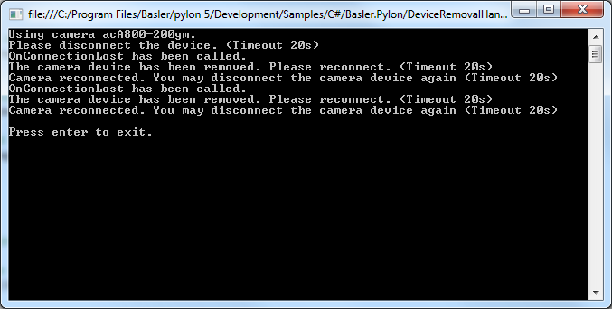
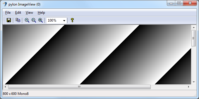
Code#
Info
You can find the sample code here.
The Camera class is used to create a camera object that opens the first camera device found. This class also provides other constructors for selecting a specific camera device, e.g., based on the device name, or serial number.
The Configuration class is used to set the acquisition mode to free running continuous acquisition when the camera is opened.
For demonstration purposes, the OnConnectionLost() event handler is added. This event is always called on a separate thread when the physical connection to the camera has been lost.
The PLTransportLayer class provides a list of all available transport layer parameters, e.g., GigE or USB 3.0 parameters. It can be used to manually set the heartbeat timeout to a shorter value when using GigE cameras.
The ImageWindow class is used to display the grabbed image on the screen.
Applicable Interfaces#
- GigE Vision
- USB3 Vision
- Camera Link
Grab#
This sample illustrates how to grab images and process images asynchronously. This means that while the application is processing a buffer, the acquisition of the next buffer is done in parallel.
The sample uses a pool of buffers. The buffers are allocated automatically. Once a buffer is filled and ready for processing, the buffer is retrieved from the stream grabber as part of a grab result. The grab result is processed and the buffer is passed back to the stream grabber by disposing the grab result. The buffer is reused and refilled.
A buffer retrieved from the stream grabber as a grab result is not overwritten in the background as long as the grab result is not disposed.
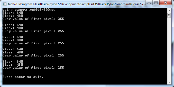
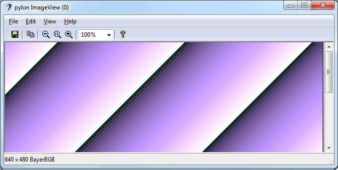
Code#
Info
You can find the sample code here.
The Camera class is used to create a camera object that opens the first camera device found. This class also provides other constructors for selecting a specific camera device, e.g., based on the device name, or serial number.
The Configuration class is used to set the acquisition mode to free running continuous acquisition when the camera is opened.
The PLCameraInstance class provides a list of all parameter names available for the Camera class instance. It is used to set the parameter MaxNumBuffer that controls the amount of buffers allocated for grabbing.
The ImageWindow class is used to display the grabbed image on the screen.
Applicable Interfaces#
- GigE Vision
- USB3 Vision
- CXP
Grab_CameraEvents#
Basler USB3 Vision and GigE Vision cameras can send event messages. For example, when a sensor exposure has finished, the camera can send an Exposure End event to the computer. The event can be received by the computer before the image data for the finished exposure has been completely transferred. This sample illustrates how to be notified when camera event message data has been received.
The event messages are retrieved automatically and processed by the Camera classes.
The information contained in event messages is exposed as parameter nodes in the camera node map and can be accessed like standard camera parameters. These nodes are updated when a camera event is received. You can register camera event handler objects that are triggered when event data has been received.
The handler object provides access to the changed parameter, but not to its source (the camera).
In this sample, we solve this problem with a derived camera class with a handler object as member.
These mechanisms are demonstrated for the Exposure End event.
The Exposure End event carries the following information:
- EventExposureEndFrameID (USB) / ExposureEndEventFrameID (GigE): Number of the image that has been exposed.
- EventExposureEndTimestamp (USB) / ExposureEndEventTimestamp (GigE): Time when the event was generated.
This sample shows how to register event handlers that indicate the arrival of events sent by the camera. For demonstration purposes, different handlers are registered for the same event.
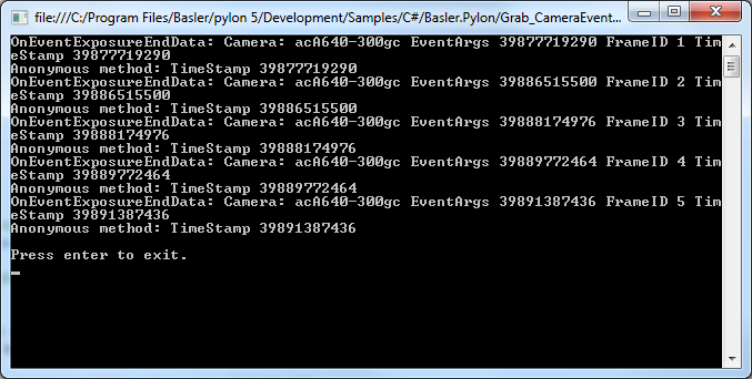
Code#
Info
You can find the sample code here.
The EventCamera class is derived from the Camera class. It is used to create a camera object that opens the first camera device found. This class provides different methods for camera configuration and event handling. Configure() is used to configure the camera for event trigger and register exposure end event handler.
The Configuration class is used to configure the camera for software trigger mode to demonstrate synchronous processing of the grab results.
The PLCameraInstance class provides a list of all parameter names available for the Camera class instance. Here, it is used to enable event notification.
The PLGigECamera and PLUsbCamera camera classes are used to access GigE and USB3 Vision specific camera features related to the Exposure End event.
The PLCamera class is used to enable Exposure End event transmission.
OnEventExposureEndData() is used to register an event handler to receive the changed FrameID value of the exposure end event.
Info
Only short processing tasks should be performed by this method. Otherwise, the event notification will block the processing of images.
The ImageWindow class is used to display the grabbed image on the screen.
Applicable Interfaces#
- GigE Vision
- USB3 Vision
Grab_ChunkImage#
Basler cameras supporting the Data Chunk feature can generate supplementary image data, e.g., frame count, time stamp, or CRC checksums, and append it to each acquired image.
This sample illustrates how to enable the Data Chunk feature, how to grab images, and how to process the appended data. When the camera is in chunk mode, it transfers data blocks partitioned into chunks. The first chunk is always the image data. If one or more data chunks are enabled, these chunks are transmitted as chunk 2, 3, and so on.
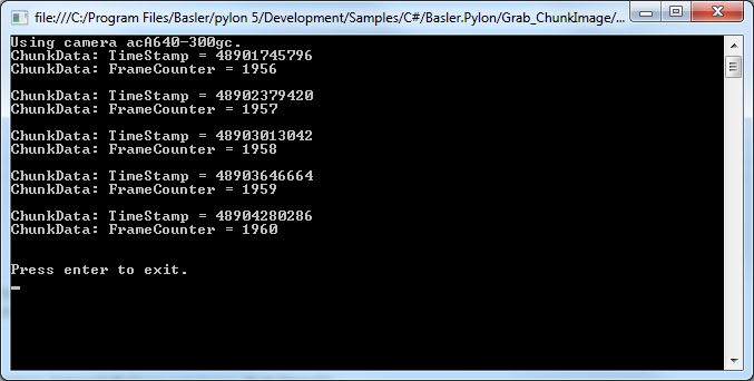
Code#
Info
You can find the sample code here.
The Camera class is used to create a camera object that opens the first camera device found. This class also provides other constructors for selecting a specific camera device, e.g., based on the device name, or serial number.
The Configuration class is used to set the acquisition mode to free running continuous acquisition when the camera is opened.
The PLCamera class is used to enable the chunk mode in general as well as specific camera chunks like timestamp, frame counter, CRC checksum, etc.
The ImageWindow class is used to display the grabbed image on the screen.
Applicable Interfaces#
- GigE Vision
- USB3 Vision
Grab_MultiCast#
This sample demonstrates how to open a camera in multicast mode and how to receive a multicast stream.
Two instances of this application must be started simultaneously on different computers.
The first application started on computer A acts as the controlling application and has full access to the GigE camera.
The second instance started on computer B opens the camera in monitor mode. This instance can't control the camera but can receive multicast streams.
To get the sample running, start the application on computer A in control mode. After computer A has begun to receive frames, start a second instance of the application on computer B in monitor mode.
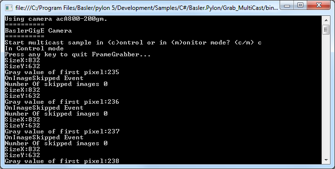
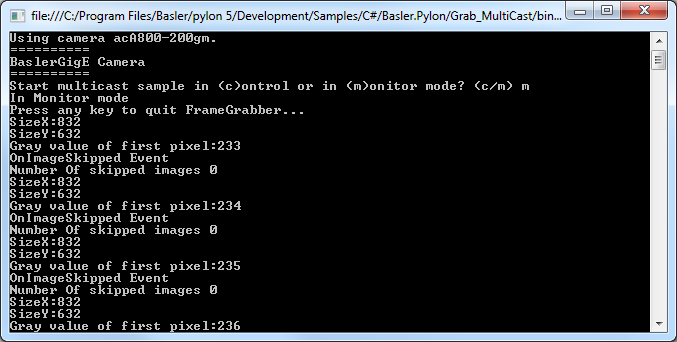
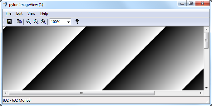
Code#
Info
You can find the sample code here.
The Camera class is used to create a camera object that opens the first GigE camera device found. This class also provides other constructors for selecting a specific camera device, e.g., based on the device name, or serial number.
The PLCameraInstance class provides a list of all parameter names available for the Camera class instance. It is used to open the camera in control or monitor mode depending on the user's input. While being opened in control mode, the control user application can adjust camera parameters and control image acquisition. While being opened in monitor mode, the monitor customer application can only read camera features and receive image data.
The PLGigEStream class provides a list of all parameter names available for the GigE stream grabber. It is used to configure the camera transmission type, e.g., for multicasting.
The PLGigECamera class provides a list of all parameter names available for GigE cameras only. It is used to configure the image area of interest and set the pixel data format.
The ImageWindow class is used to display the grabbed image on the screen.
Applicable Interfaces#
- GigE Vision
Grab_Strategies#
This sample demonstrates the use of the following Camera grab strategies:
- GrabStrategy.OneByOne
- GrabStrategy.LatestImages
When the "OneByOne" grab strategy is used, images are processed in the order of their acquisition. This strategy can be useful when all grabbed images need to be processed, e.g., in production and quality inspection applications.
The "LatestImages" strategy can be useful when the acquired images are only displayed on screen. If the processor has been busy for a while and images could not be displayed automatically, the latest image is displayed when processing time is available again.
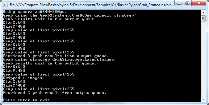
Code#
Info
You can find the sample code here.
The Camera class is used to create a camera object that opens the first camera device found. This class also provides other constructors for selecting a specific camera device, e.g., based on the device name, or serial number.
The PLCameraInstance class provides a list of all parameter names available for the Camera class instance. It is used to enable the grabbing of camera events in general and control the buffer size of the output queue.
The Configuration class is used to configure the camera for software trigger mode.
The PLStream class provides a list of all parameter names available for the stream grabber. It is used to set the MaxNumBuffer parameter that controls the count of buffers allocated for grabbing. The default value of this parameter is 10.
The GrabStrategy.OneByOne and GrabStrategy.LatestImages grab strategies are applied by passing them as an argument to Start(), which is called on the stream grabber.
Applicable Interfaces#
- GigE Vision
- USB3 Vision
- CXP
Grab_UsingActionCommand#
This sample shows how to issue a GigE Vision action command to multiple cameras. By using an action command, multiple cameras can be triggered at the same time as opposed to software triggering where each camera has to be triggered individually.
To make the configuration of multiple cameras and the execution of the action commands easier, this sample uses the ActionCommandTrigger class.
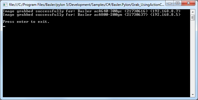
Code#
Info
You can find the sample code here.
The CameraFinder class provides a list of all found GigE camera devices.
The ActionCommandTrigger class provides simplified access to GigE action commands. It is used to configure the DeviceKey, GroupKey, and GroupMask parameters for cameras automatically. It also configures the camera's trigger and sets the trigger source to Action1. In addition, there are some static methods for issuing and scheduling an action command.
Applicable Interfaces#
- GigE Vision
Grab_UsingBufferFactory#
This sample demonstrates how to use a user-provided buffer factory. Using a buffer factory is optional and intended for advanced use cases only. A buffer factory is only necessary if you want to grab into externally supplied buffers.
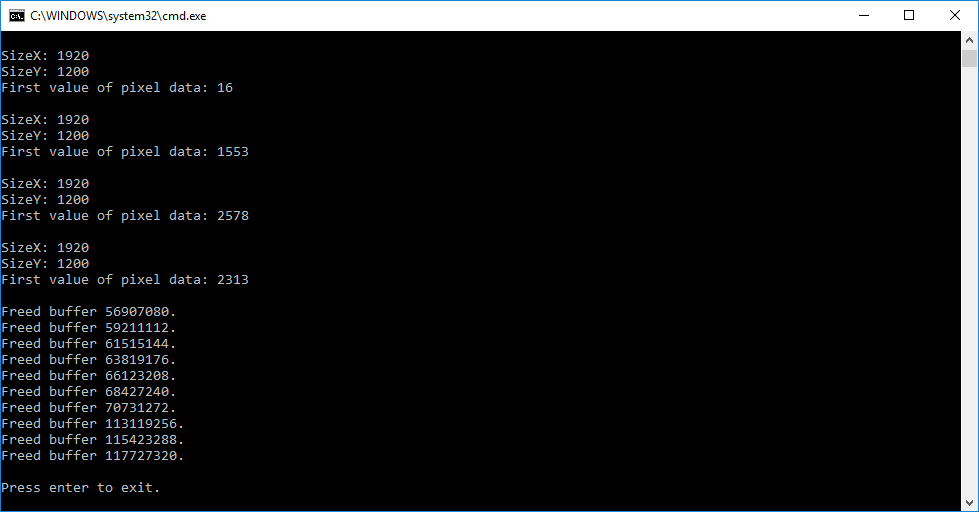
Code#
Info
You can find the sample code here.
The MyBufferFactory class demonstrates how to use a user-provided buffer factory.
The buffer factory must be created before streaming is started in order to allocate the buffer memory.
Note that the .NET garbage collector automatically manages the release of allocated memory for your application.
The Camera class is used to create a camera object that opens the first camera device found. This class also provides other constructors for selecting a specific camera device, e.g., based on the device name or serial number.
Applicable Interfaces#
- GigE Vision
- USB3 Vision
- CXP
Grab_UsingExposureEndEvent#
This sample shows how to use the Exposure End event to speed up the image acquisition. For example, when a sensor exposure is finished, the camera can send an Exposure End event to the computer. The computer can receive the event before the image data has been completely transferred. This allows you to avoid unnecessary delays, e.g., when an imaged object is moved further before the related image data transfer is complete.
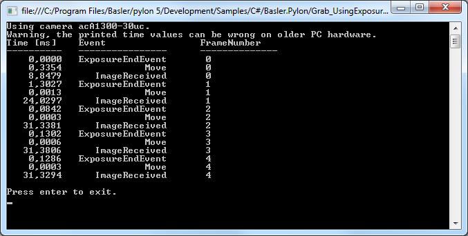
Code#
Info
You can find the sample code here.
The Camera class is used to create a camera object that opens the first camera device found. This class also provides other constructors for selecting a specific camera device, e.g., based on the device name, or serial number.
The Configure() helper function is used to configure the camera for sending events.
The PLCameraInstance class provides a list of all parameter names available for the Camera class instance. Here, it is used to enable event notification.
The PLCamera class is used to configure and enable the sending of Exposure End, Event Overrun and Frame Start Overtrigger events.
In this sample, different event handlers are used to receive the grabbed image data and the camera events.
Applicable Interfaces#
- GigE Vision
- USB3 Vision
Grab_UsingGrabLoopThread#
This sample illustrates how to grab and process images using the grab loop thread provided by the Camera class.
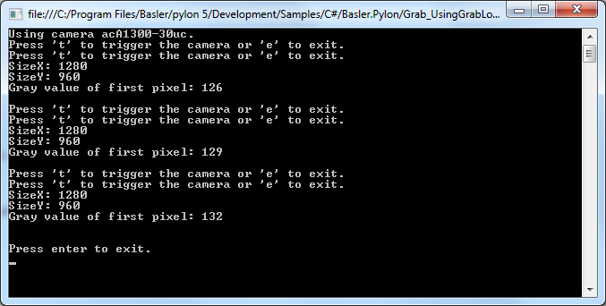
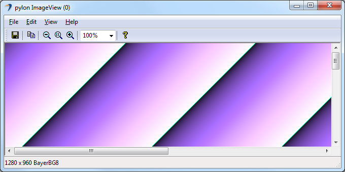
Code#
Info
You can find the sample code here.
The Camera class is used to create a camera object that opens the first camera device found. This class also provides other constructors for selecting a specific camera device, e.g., based on the device name, or serial number.
The PLCameraInstance class provides a list of all parameter names available for the Camera class instance. It is used to enable the grabbing of camera events in general and control the buffer size of the output queue.
The Configuration class is used to configure the camera for software trigger mode.
Image grabbing is started by using an additional grab loop thread provided by the stream grabber. This is done by setting the grabLoopType parameter to GrabLoop.ProvidedByStreamGrabber. The grab results are delivered to the OnImageGrabbed image event handler. The "OneByOne" default grab strategy is used.
The ImageWindow class is used to display the grabbed image on the screen.
The ImagePersistence class is used to save the grabbed image to a Bitmap image file.
Applicable Interfaces#
- GigE Vision
- USB3 Vision
- CXP
Grab_UsingSequencer#
This sample shows how to grab images using the Sequencer feature of a camera. Three sequence sets are used for image acquisition. Each sequence set uses a different image height.
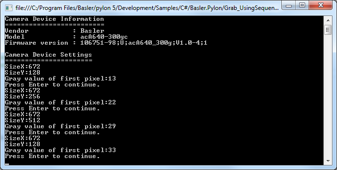
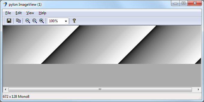
Code#
Info
You can find the sample code here.
The Camera class is used to create a camera object that opens the first camera device found. This class also provides other constructors for selecting a specific camera device, e.g., based on the device name, or serial number.
The Configuration class is used to configure the camera for software trigger mode.
The PLCamera class is used to enable and configure the camera Sequencer feature.
The ImageWindow class is used to display the grabbed image on the screen.
Applicable Interfaces#
- GigE Vision
- USB3 Vision
GUISampleMultiCam#
This sample demonstrates how to operate multiple cameras using an Windows Forms GUI together with the pylon .NET API.
The sample demonstrates different techniques for opening a camera, e.g., by using its serial number or user device ID. It also contains an image-processing example and shows how to handle device disconnections.
The sample covers single and continuous image acquisition using software as well as hardware triggering.
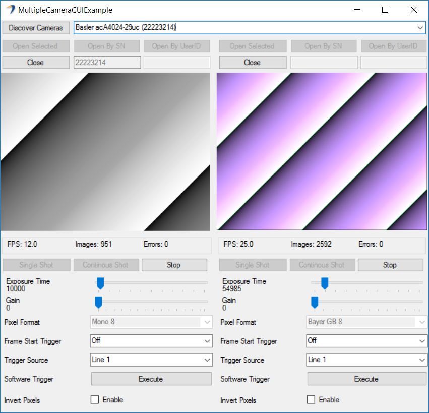
Code#
Info
You can find the sample code here.
When the Discover Cameras button is clicked, the UpdateDeviceList() function in the MainForm class is called, which in turn calls the CameraFinder.Enumerate() function to enumerate all attached devices.
By clicking the Open Selected button, the SelectByCameraInfo() function is called to create a new device info object.
Then, the OpenCamera() function in the GUICamera class is called to create a camera object and open the selected camera. In addition, event handlers for image grabbing and device removal are registered.
Cameras can be opened by clicking the Open by SN (SN = serial number) or Open by User ID button. The latter assumes that you have already assigned a user ID to the camera, e.g., in the pylon Viewer or via the pylon API.
After a camera has been opened, the following GUI elements become available:
- Single Shot, Continuous Shot, Stop, and Execute (for executing a software trigger) buttons
- Exposure Time and Gain sliders
- Pixel Format, Trigger Mode, and Trigger Source drop-down lists
- Invert Pixels check box
By clicking the Single Shot button, the SingleShot() function is called. To grab a single image, the stream grabber Start() function is called with the following arguments:
camera.StreamGrabber.Start(1, GrabStrategy.OneByOne, GrabLoop.ProvidedByStreamGrabber);
When the image is received, pylon will call the OnImageGrabbed() handler and the image will be displayed.
By clicking the Continuous Shot button, the ContinuousShot() function is called. To grab images continuously, the stream grabber Start() function is called with the following arguments:
camera.StreamGrabber.Start(GrabStrategy.OneByOne, GrabLoop.ProvidedByStreamGrabber);
In this case, the camera will grab images until the stream grabber Stop() function is called.
When a new image is received, pylon will call the OnImageGrabbed() handler and the grabbed images will be displayed continuously.
This sample also demonstrates the triggering of cameras by using a software trigger. For this purpose, the Trigger Mode parameter has to be set to On, and the Trigger Source parameter has to be set to Software. When starting a single or a continuous image acquisition, the camera will then be waiting for a software trigger.
By clicking the Execute button, the SoftwareTrigger() function will be called, which will execute a software trigger.
For triggering the camera by hardware trigger, set Trigger Mode to On and Trigger Source to, e.g., Line1. When starting a single or a continuous image acquisition, the camera will then be waiting for a hardware trigger.
By selecting the Invert Pixels check box, an example of image processing will be shown. In the example, the pixel data will be inverted. This is done in the InvertColors() function, which is called from OnImageGrabbed().
Finally, this sample also shows the use of Device Removal callbacks. If an already opened camera is disconnected, the OnDeviceRemoved() function is called. In turn, the OnCameraDisconnected() function will be called to inform the user about the disconnected camera.
Applicable Interfaces#
- GigE Vision
- USB3 Vision
- CXP
ParametrizeCamera#
This sample illustrates how to read and write different camera parameter types.
For camera configuration and for accessing other parameters, the pylon API uses the technologies defined by the GenICam standard. The standard also defines a format for camera description files.
These files describe the configuration interface of GenICam-compliant cameras. The description files are written in XML and describe camera registers, their interdependencies, and all other information needed to access high-level features. This includes features such as Gain, Exposure Time, or Pixel Format. The features are accessed by means of low level register read and write operations.
The elements of a camera description file are represented as parameter objects. For example, a parameter object can represent a single camera register, a camera parameter such as Gain, or a set of parameter values.
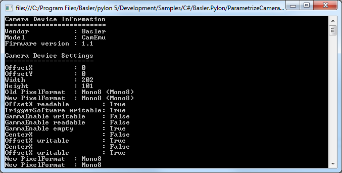
Code#
Info
You can find the sample code here.
The Camera class is used to create a camera object that opens the first camera device found. This class also provides other constructors for selecting a specific camera device, e.g., based on the device name, or serial number.
The PLCamera class is used to configure camera features such as Width, Height, OffsetX, OffsetY, PixelFormat, etc.
The PLUsbCamera class is used to configure features compatible with the SFNC version 2.0, e.g., the feature Gain available on USB3 Vision cameras.
Applicable Interfaces#
- GigE Vision
- USB3 Vision
- Camera Link
- CXP
ParametrizeCamera_AutoFunctions#
This sample illustrates how to use the Auto Functions feature of Basler cameras.
Info
Different camera families implement different versions of the Standard Feature Naming Convention (SFNC). That's why the name and the type of the parameters used can be different.
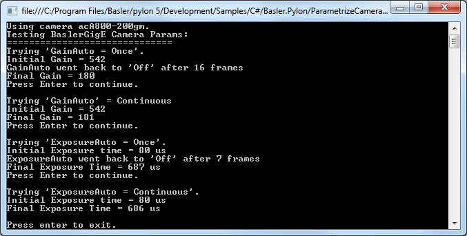
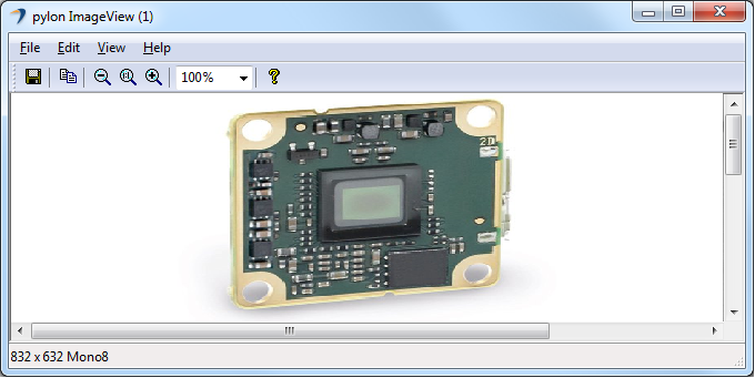
Code#
Info
You can find the sample code here.
The Camera class is used to create a camera object that opens the first camera device found. This class also provides other constructors for selecting a specific camera device, e.g., based on the device name, or serial number.
The PLCamera class is used to demonstrate the configuration of different camera features:
AutoGainOnce(): Carries out luminance control by using the Gain Auto auto function in the Once operating mode.AutoGainContinuous(): Carries out luminance control by using the Gain Auto auto function in the Continuous operating mode.AutoExposureOnce(): Carries out luminance control by using the Exposure Auto auto function in the Once operating mode.AutoExposureContinuous(): Carries out luminance control by using the Exposure Auto auto function in the Continuous operating mode.AutoWhiteBalance(): Carries out white balance using the Balance White Auto auto function. Note: Only color cameras support this auto function.
Applicable Interfaces#
- GigE Vision
- USB3 Vision
ParametrizeCamera_AutomaticImageAdjustment#
This sample illustrates how to mimic the Automatic Image Adjustment button of the Basler pylon Viewer.
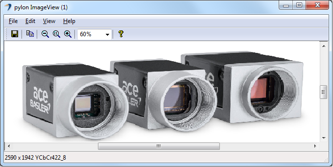
Code#
Info
You can find the sample code here.
The Camera class is used to create a camera object that opens the first camera device found. This class also provides other constructors for selecting a specific camera device, e.g., based on the device name, or serial number.
The PLCamera class is used to demonstrate the usage of automatic image adjustment features like GainAuto, ExposureAuto and BalanceWhiteAuto. In addition, features related to the color image quality like Gamma and LightSourcePreset are used.
The ImageWindow class is used to display the grabbed image on the screen.
Applicable Interfaces#
- GigE Vision
- USB3 Vision
ParametrizeCamera_Configurations#
This sample shows how to use configuration event handlers by applying the standard configurations and registering sample configuration event handlers.
If the configuration event handler is registered, the registered methods are called when the state of the camera objects changes, e.g., when the camera object is opened or closed. In pylon.NET, a configuration event handler is a method that parametrizes the camera.
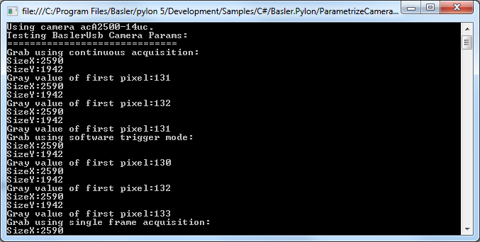
Code#
Info
You can find the sample code here.
The Camera class is used to create a camera object that opens the first camera device found. This class also provides other constructors for selecting a specific camera device, e.g., based on the device name, or serial number.
The Configuration class is used to demonstrate the usage of different configuration event handlers.
The Configuration.AcquireContinuous handler is a standard configuration event handler to configure the camera for continuous acquisition.
The Configuration.SoftwareTrigger handler is a standard configuration event handler to configure the camera for software triggering.
The Configuration.AcquireSingleFrame handler is a standard configuration event handler to configure the camera for single frame acquisition.
The PixelFormatAndAoiConfiguration handler is a custom event handler for pixel format and area of interest configuration.
Applicable Interfaces#
- GigE Vision
- USB3 Vision
- CXP
ParametrizeCamera_LoadAndSave#
This sample application demonstrates how to save or load the features of a camera to or from a file.
Code#
Info
You can find the sample code here.
The Camera class is used to create a camera object that opens the first camera device found. This class also provides other constructors for selecting a specific camera device, e.g., based on the device name, or serial number.
The Parameters interface returns a parameter collection of the camera for accessing all parameters. It is used to access the Save() and the Load() functions which allow saving or loading of camera parameters to or from a file. This feature can be used to transfer the configuration of a "reference" camera to other cameras.
Applicable Interfaces#
- GigE Vision
- USB3 Vision
- Camera Link
ParametrizeCamera_LookupTable#
This sample program demonstrates the use of the Luminance Lookup Table (LUT) feature.
Code#
Info
You can find the sample code here.
The Camera class is used to create a camera object that opens the first camera device found. This class also provides other constructors for selecting a specific camera device, e.g., based on the device name, or serial number.
The PLCamera class is used to enable and configure all parameters related to the lookup table camera feature.
Applicable Interfaces#
- GigE Vision
- USB3 Vision
- Camera Link
ParametrizeCamera_UserSets#
This sample application demonstrates how to use user sets (also called "configuration sets") and how to configure the camera to start up with the user-defined settings of user set 1.
You can also configure your camera using the pylon Viewer and store your custom settings in a user set of your choice.
Info
Executing this sample will overwrite all current settings in user set 1.
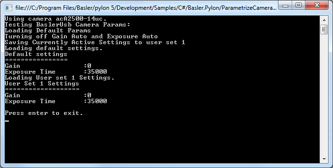
Code#
Info
You can find the sample code here.
The Camera class is used to create a camera object that opens the first camera device found. This class also provides other constructors for selecting a specific camera device, e.g., based on the device name, or serial number.
The PLCamera class is used to demonstrate the use of the camera user sets feature.
Applicable Interfaces#
- GigE Vision
- USB3 Vision
- Camera Link
- CXP
PylonLiveView#
This sample demonstrates the use of a GUI to enumerate attached cameras, to configure a camera, to start and stop grabbing and to display grabbed images.
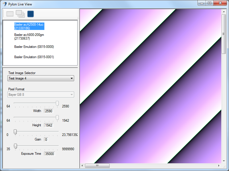
Code#
The MainForm class contains the implementation of the main controls and events to be used.
When a camera device is selected in the device list, the OnCameraOpened() callback is called and the camera device is opened.
When the One Shot button is clicked, the toolStripButtonOneShot_Click() callback is called, which in turn calls OneShot() to start the grabbing of one image. The PLCamera class is used to select the SingleFrame acquisition mode. The "OneByOne" default grab strategy is applied while an additional grab loop thread provided by the stream grabber is used.
The grab results are delivered to the OnImageGrabbed() image event handler.
When the Continuous Shot button is clicked, the toolStripButtonContinuousShot_Click() callback is called, which in turn calls ContinuousShot() to start the grabbing of images until grabbing is stopped. The PLCamera class is used to select the Continuous acquisition mode. The "OneByOne" default grab strategy is applied while an additional grab loop thread provided by the stream grabber is used.
The grab results are delivered to the OnImageGrabbed() image event handler.
When the Stop Grab button is clicked, the toolStripButtonStop_Click() callback is called, which in turn calls Stop() to stop the grabbing of images.
Applicable Interfaces#
- GigE Vision
- USB3 Vision
- CXP
Utility_AnnounceRemoteDevice#
This sample illustrates how to discover and work with GigE Vision cameras that are behind a router.
When a camera is behind a router, the router will prevent any broadcast device discovery messages to pass through and reach the camera. In turn, this will usually prevent the camera from being discovered by the pylon IP Configurator, the pylon Viewer, or a customer application.
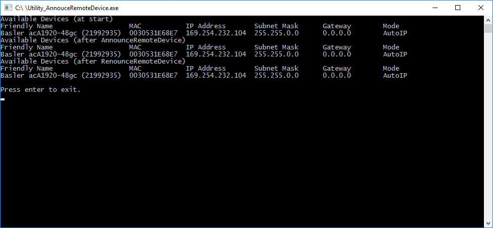
Code#
Info
You can find the sample code here.
The CameraFinder class is used to discover all GigE Vision cameras that are not connected behind a router, i.e., cameras that can be accessed by broadcast device discovery messages.
The IpConfigurator class is used to access a GigE Vision camera behind a router. For that purpose, the AnnounceRemoteDevice() function is used, which sends a unicast device discovery message to the specific IP address of the camera.
Applicable Interfaces#
- GigE Vision
Utility_GrabAvi#
This sample illustrates how to create a video file in Audio Video Interleave (AVI) format. Note: AVI is best for recording high-quality lossless videos because it allows you to record without compression. The disadvantage is that the file size is limited to 2 GB. Once that threshold is reached, the recording stops and an error message is displayed.
Code#
Info
You can find the sample code here.
The Camera class is used to create a camera object that opens the first camera device found. This class also provides other constructors for selecting a specific camera device, e.g., based on the device name, or serial number.
The PLCamera class is used to set the region of interest and the pixel format of the camera.
The PLCameraInstance class provides a list of all parameter names available for the Camera class instance. It is used to set the parameter MaxNumBuffer that controls the amount of buffers allocated for grabbing.
The AviVideoWriter class is used to create and save AVI video file to the computer's hard drive.
Applicable Interfaces#
- GigE Vision
- USB3 Vision
- CXP
Utility_GrabVideo#
This sample demonstrates how to create a video file in MP4 format. It is presumed that the pylon Supplementary Package for MPEG-4 is already installed.
Info
There are no file size restrictions when recording MP4 videos. However, the MP4 format always compresses data to a certain extent, which results in loss of detail.
Code#
Info
You can find the sample code here.
The Camera class is used to create a camera object that opens the first camera device found. This class also provides other constructors for selecting a specific camera device, e.g., based on the device name, or serial number.
The PLCamera class is used to set the region of interest and the pixel format of the camera.
The PLCameraInstance class provides a list of all parameter names available for the Camera class instance. It is used to set the parameter MaxNumBuffer that controls the amount of buffers allocated for grabbing.
The VideoWriter class is used to create and save MP4 video file to the computer's hard drive.
The PLVideoWriter class provides a list of parameter names available for the video writer class. It is used to set the quality of the resulting compressed stream. The quality has a direct influence on the resulting bit rate. The optimal bit rate is calculated based on the input values height, width, and playback frame. This is then normalized to the quality value range 1-–100, where 100 corresponds to the optimum bit rate and 1 to the lowest bit rate.
Applicable Interfaces#
- GigE Vision
- USB3 Vision
- CXP
Utility_ImageDecompressor#
This sample illustrates how to enable and use the Basler Compression Beyond feature in Basler ace 2 GigE and Basler ace 2 USB 3.0 cameras.
This sample also demonstrates how to decompress the images using the CImageDecompressor class.
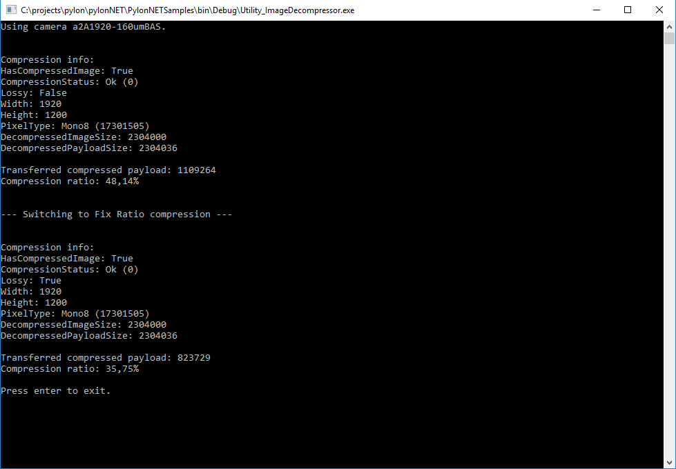
Code#
Info
You can find the sample code here.
The Camera class is used to create a camera object that opens the first camera device found. This class also provides other constructors for selecting a specific camera device, e.g., based on the device name, or serial number.
The Configuration class is used to set the acquisition mode to a single image acquisition when the camera is opened.
The ImageDecompressor class is used to decompress grabbed images. In this sample, compression and decompression are demonstrated, using lossless and lossy algorithms.
The CompressionInfo class is used to fetch information of a compressed image for display.
The ImageWindow class is used to display the grabbed image on the screen.
Applicable Interfaces#
- GigE Vision
- USB3 Vision
Utility_IpConfig#
This sample demonstrates how to configure the IP address of a GigE Vision camera. The functionalities described in this sample are similar to those used in the pylon IP Configurator.
In addition, this sample can be used to automatically and programmatically configure multiple GigE Vision cameras. As the sample accepts command line arguments, it can be directly executed, e.g., from a batch script file.
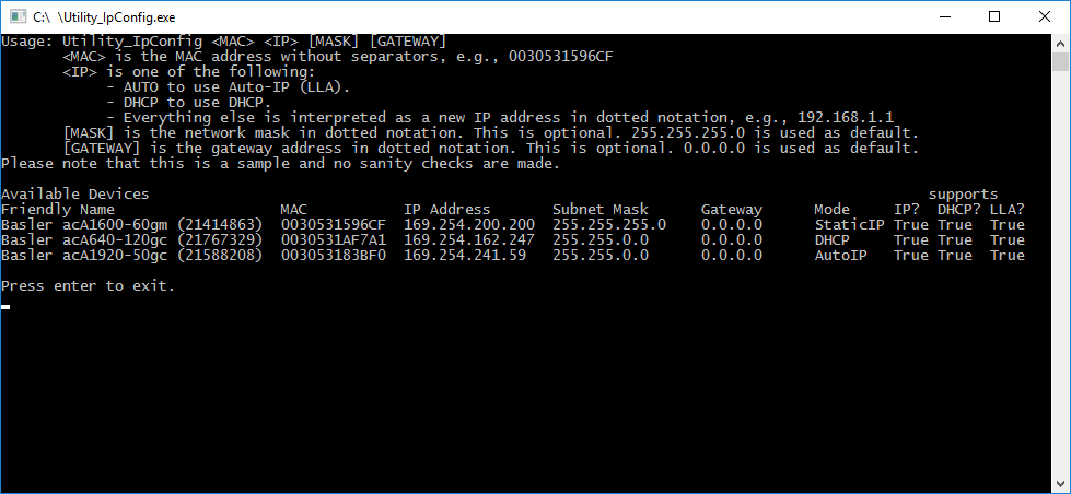
Code#
Info
You can find the sample code here.
The IpConfigurator class is used to discover all GigE Vision cameras independent of their current IP address configuration. For that purpose, the EnumerateAllDevices() function is used.
To set a new IP address of a GigE Vision camera, the ChangeIpConfiguration() function is used.
Applicable Interfaces#
- GigE Vision
VBGrab#
This sample illustrates how to grab images and process images asynchronously.
This means that while the application is processing a buffer, the acquisition of the next buffer is done in parallel. The sample uses a pool of buffers. The buffers are allocated automatically. Once a buffer is filled and ready for processing, the buffer is retrieved from the stream grabber as part of a grab result.
The grab result is processed and the buffer is passed back to the stream grabber by disposing the grab result. The buffer is reused and refilled. A buffer retrieved from the stream grabber as a grab result is not overwritten in the background as long as the grab result is not disposed.
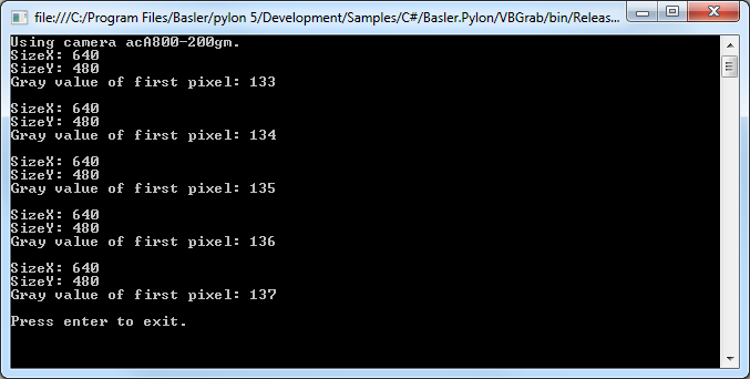
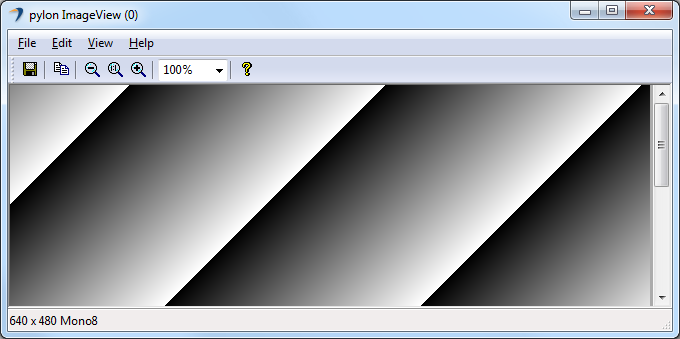
Code#
Info
You can find the sample code here.
The Camera class is used to create a camera object that opens the first camera device found. This class also provides other constructors for selecting a specific camera device, e.g., based on the device name, or serial number.
The Configuration class is used to set the acquisition mode to free running continuous acquisition when the camera is opened.
The PLCameraInstance class provides a list of all parameter names available for the Camera class instance. It is used to set the parameter MaxNumBuffer that controls the amount of buffers allocated for grabbing.
The ImageWindow class is used to display the grabbed image on the screen.
Applicable Interfaces#
- GigE Vision
- USB3 Vision
- CXP
VBParametrizeCamera#
This sample illustrates how to read and write different camera parameter types.
For camera configuration and for accessing other parameters, the pylon API uses the technologies defined by the GenICam standard. The standard also defines a format for camera description files.
These files describe the configuration interface of GenICam-compliant cameras. The description files are written in XML and describe camera registers, their interdependencies, and all other information needed to access high-level features. This includes features such as Gain, Exposure Time, or Pixel Format. The features are accessed by means of low level register read and write operations.
The elements of a camera description file are represented as parameter objects. For example, a parameter object can represent a single camera register, a camera parameter such as Gain, or a set of parameter values.
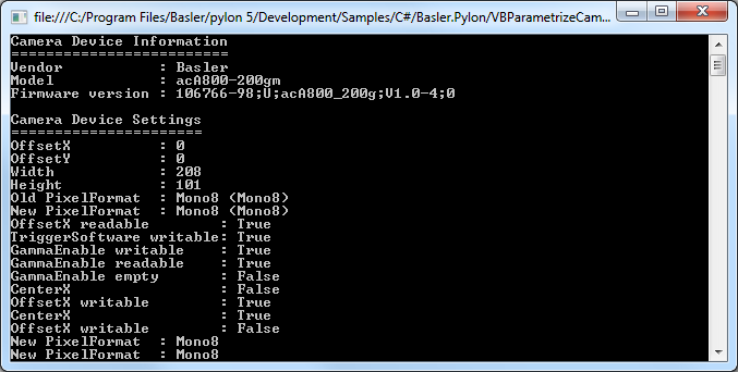
Code#
Info
You can find the sample code here.
The Camera class is used to create a camera object that opens the first camera device found. This class also provides other constructors for selecting a specific camera device, e.g., based on the device name, or serial number.
The PLCamera class is used to demonstrate the configuration of different camera features such as Width, Height, OffsetX, OffsetY, PixelFormat, etc.
The PLUsbCamera class is used to configure features compatible with the SFNC version 2.0, e.g., the feature Gain available on USB3 Vision cameras.
Applicable Interfaces#
- GigE Vision
- USB3 Vision
- Camera Link
- CXP