
Operator Library: Hardware Platform
DFLed 算子代表数据转发协议下的前面板 QSFP28 光纤端口 LED 控制。DFLed 算子只能用于数据转发 (DF) 应用,前提是 AppletProperties 算子中的 FiberProtocol0 和 FiberProtocol1 参数设置为 DataForwarding。
该 LED 为双色 LED,允许分别控制 绿色和红色 LED,即可以表示 4 种光学状态:关闭、绿色、 红色、橙色(红 + 绿点亮)。为了简化设计中的使用,红色和绿色 LED 可以通过 2 个不同的算子分别进行控制。
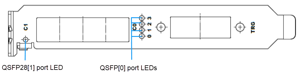
QSFP28[0] 端口支持 4 个绿色和 4 个红色 LED,即每个光纤通道都拥有两种颜色中各一个排他性 LED。QSFP28[1] 端口 只有 1 个 LED,该 LED 由所有 4 个光纤通道共用,即 1 个绿色和 1 个红色 LED。
| 适用于 Hardware Platform |
|---|
| imaFlex 2 Dual 100 |
资源
该算子将 FiberConnection 参数设置镜像到 对话框中作为只读参数。如果您从 菜单打开 对话框,则可以看到 FPGA 设备资源。设备资源是只读的。
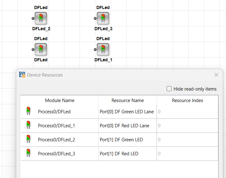
该资源属于以下 types 之一:
-
Port[0] DF 绿色 LED 通道,索引为 0 到 3
-
Port[0] DF 红色 LED 通道,索引为 0 到 3
-
Port[1] DF 绿色 LED,索引为 0 到 0
-
Port[1] DF 红色 LED,索引为 0 到 0
每个资源专属于单个 算子。因此,两个算子绝不能具有相同的端口和通道映射。如果出现这种情况, 设计规则检查 (DRC) 会提供错误消息。
| Link Parameter | Input Link I |
|---|---|
| Bit Width | 1 |
| Arithmetic | unsigned |
| Parallelism | 1 |
| Kernel Columns | 1 |
| Kernel Rows | 1 |
| Img Protocol | VALT_SIGNAL |
| Color Format | VAF_GRAY |
| Color Flavor | FL_NONE |
| Max. Img Width | any |
| Max. Img Height | any |
| FiberConnection | |
|---|---|
| 键入 | 静态写入参数 |
| 默认 | port_0_lane_0_green |
| 范围 | {port_0_lane_0_green, port_0_lane_1_green, port_0_lane_2_green, port_0_lane_3_green, port_0_lane_0_red, port_0_lane_1_red, port_0_lane_2_red, port_0_lane_3_red, port_1_green, port_1_red} |
|
FiberConnection 参数定义了相应 LED 所指的 QSFP28 光纤端口和通道,包括 LED 颜色(绿色或红色)。 仅当该端口的 AppletProperties 算子中的 FiberProtocol 参数 设置为 DataForwarding 且未设置为 CoF 时, 才能使用所选的 QSFP28 端口。 当 FiberProtocol 设置为 CoF 且 DFLed 算子尝试映射到该光纤端口时,设计规则检查 (DRC) 将 生成相应的错误消息。在这种情况下, FiberConnection 参数将被标记 为冲突(红色),将鼠标悬停在其上方将显示解释冲突的快速提示帮助消息。 只能有一个 DFLed 算子在同一通道和同一颜色上使用相同的硬件 QSFP28 端口。多个算子之间的映射在整个设计中必须是唯一的。 |
|
 上一页
上一页

