Operator Library: Signal
The operator generates a periodic signal at its output. Moreover, the pulse generation can be controlled by input signals. The period time and the number of pulses to be generated can be defined using parameters.
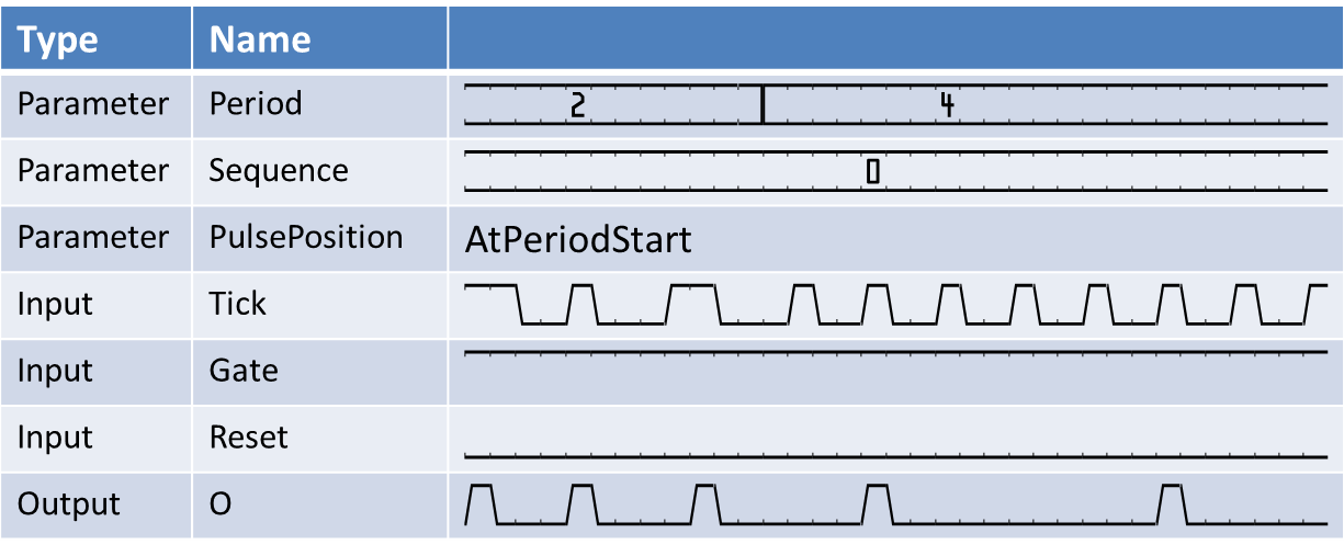
The period is defined using the parameter Period. The period is dynamic. Its range is defined by the parameter PeriodBits. In the following figure, the generation of pulses with period lengths eight and four are shown.
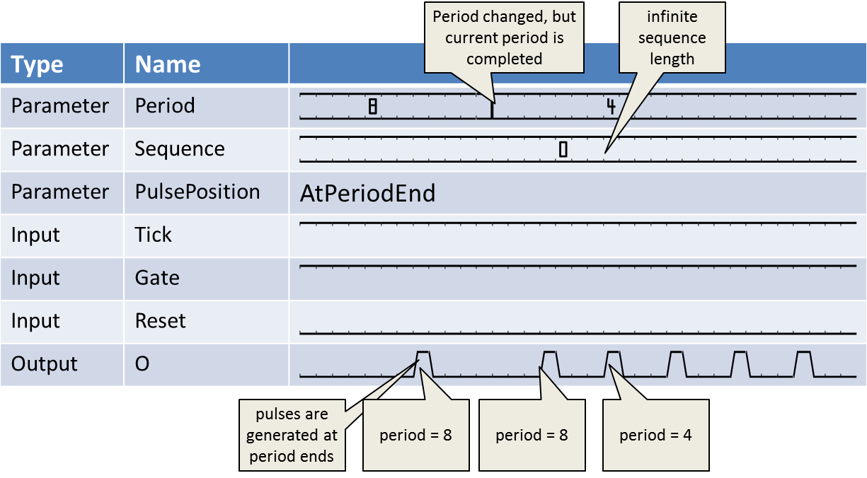
Changes at the Period parameter will only be applied to the operator when the generation of the current period is completed. This ensures periods in the parametrized lengths only.
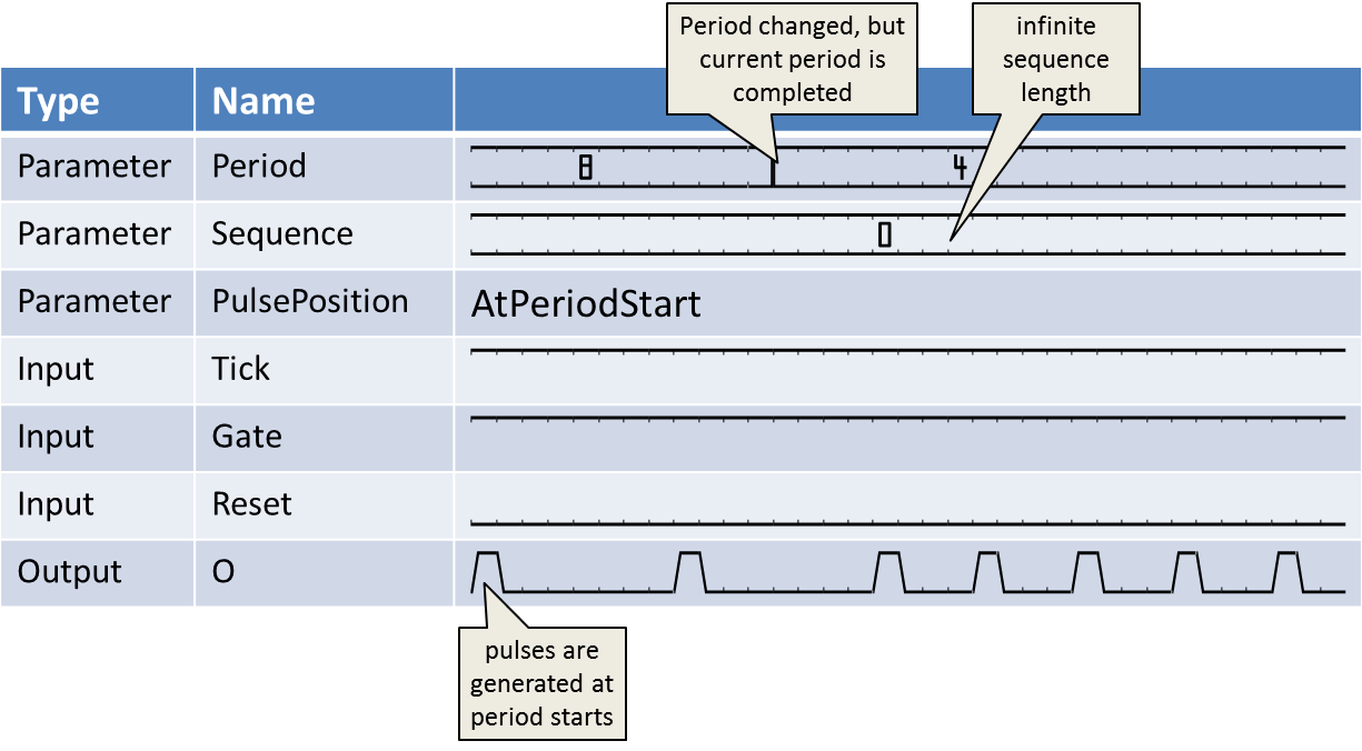
The pulse generation can either be at the end of the period or at the start as is controlled using the parameter PulsePosition. The next figure shows the generation at the start of a sequence.
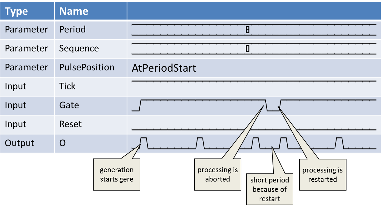
By use of the Gate input link, the generation can be controlled. Periods are generated only if input Gate is active (high). The rising edge at the Gate input starts the period generation. A falling edge at the Gate input link immediately aborts the generation. Currently processed periods might not be completed in this case. Moreover, a new rising edge can yield a short period. This is shown in the following waveform.
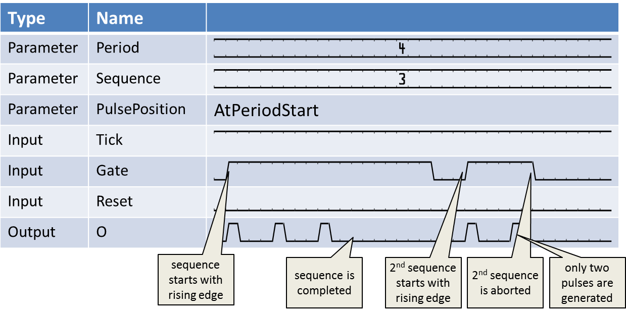
The parameter SequenceLength facilitates the generation of sequences. In the previous figures, the parameter was set to 0 which results in an infinite sequence length. If you set the parameter to values > 0, the operator will only generate the number of parametrized periods. In the following waveform, the sequence length is set to 3 with a period set to 4. As can be seen in the waveform, the period generation is stopped after the third period. A new rising edge at the Gate input will start a new sequence. Sequences can be aborted if Gate turns to 0.
In many applications, an infinite sequence generation of the operator is required. In this case, set parameter SequenceLength to 0 and connect operator VCC to the Gate input. The operator will then start its period generation at process start e.g. acquisition start.
The period time is measured in Ticks being high. Tick is a signal input and can be used like a pre-scaler. For every high value at the Tick input, the period time is counted. The following waveform shows the behavior of the Tick input to the period generation. In most cases, the Tick input is not required. Tie it to operator VCC in this case.
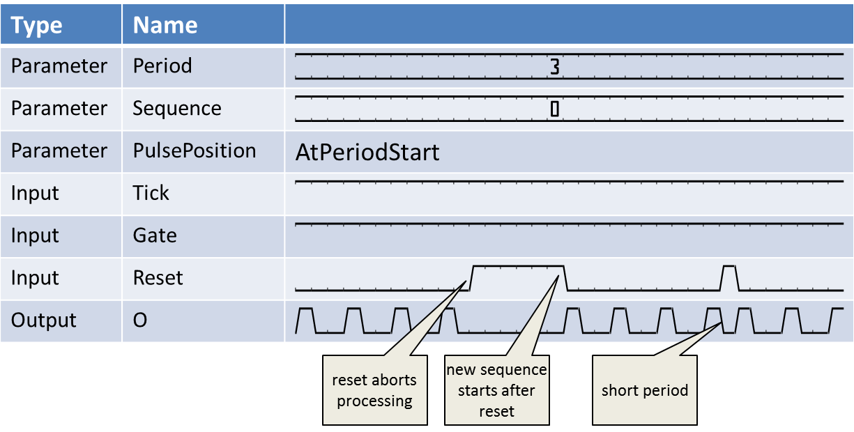
The Reset input link is used to reset the operator. This is useful if a long period or sequence has to be cancelled. In the next figure, the use of Reset is illustrated.
![[Note]](../common/images/admon/note.png) |
Use the Reset input instead of setting Period to 0 |
|---|---|
|
If Period is set to 0, a change of the period back to an active state may take very long (2^PeriodBit-1 clock cycles). It is therefore recommended to use the Reset input in this cases. |
This operator is excluded from the VisualApplets functional simulation.
| Property | 值 |
|---|---|
| Operator Type | O |
| Input Links | Tick, signal input Gate, signal input Reset, signal input |
| Output Link | O, signal input |
| Link Parameter | Input Link Tick | Input Link Gate | Input Link Reset | Output Link O |
|---|---|---|---|---|
| Bit Width | 1 | 1 | 1 | 1 |
| Arithmetic | unsigned | unsigned | unsigned | unsigned |
| Parallelism | 1 | 1 | 1 | 1 |
| Kernel Columns | 1 | 1 | 1 | 1 |
| Kernel Rows | 1 | 1 | 1 | 1 |
| Img Protocol | VALT_SIGNAL | VALT_SIGNAL | VALT_SIGNAL | VALT_SIGNAL |
| Color Format | VAF_GRAY | VAF_GRAY | VAF_GRAY | VAF_GRAY |
| Color Flavor | FL_NONE | FL_NONE | FL_NONE | FL_NONE |
| Max. Img Width | any | any | any | as Gate |
| Max. Img Height | any | any | any | as Gate |
| PeriodBits | |
|---|---|
| 键入 | static parameter |
| 默认 | 16 |
| 范围 | [1, 64] |
|
Number of bits required to encode the value specified by Period. This parameter is enabled only if parameter Period is dynamic. |
|
| Period | |
|---|---|
| 键入 | static/dynamic read/write parameter |
| 默认 | 65535 |
| 范围 | [0, 2^PeriodBits-1] if dynamic, [1,2^64-1] if static |
|
Defines the period time of the generated pulses. Do not use the following cases: If period set to 1, the operator will output a constant one without any gaps. Number of bits required to encode the value specified by If set to 0, the operator will not output any pulses. |
|
| SequenceBits | |
|---|---|
| 键入 | static parameter |
| 默认 | 16 |
| 范围 | [1, 64] |
|
Number of bits required to encode the value specified by Sequence. This parameter is enabled only if parameter Sequence is dynamic. |
|
| Sequence | |
|---|---|
| 键入 | static/dynamic read/write parameter |
| 默认 | 0 |
| 范围 | [1, 2^SequenceBits-1] if dynamic, [1,2^64-1] if static |
|
Defines the sequence length i.e. the number of pulses generated for each pulse at the Gate input link. |
|
| PulsePosition | |
|---|---|
| 键入 | static parameter |
| 默认 | AtPeriodEnd |
| 范围 | {AtPeriodStart, AtPeriodEnd} |
|
The output pulse can either be at the start of each period or at the end of each period. |
|
The use of operator Generate is shown in the following examples:
-
An example for hardware self test of DMA, RAM, GPIOs, Trigger and LEDs.
-
Example - While image timing is provided by a generator the designs data flow can be analyzed.
-
'Area Scan Trigger for microEnable 5 marathon'
An area scan trigger is presented. External sources, an internal frequency generator or software trigger pulses can be used for trigger generation.
-
'Area Scan Trigger for microEnable 5 marathon VCX QP'
An area scan trigger for CoaXPress is presented. External sources, an internal frequency generator or software trigger pulses can be used for trigger generation.
-
'Area Scan Trigger for imaFlex CXP-12 Quad'
An area scan trigger for CoaXPress12 is presented. External sources, an internal frequency generator or software trigger pulses can be used for trigger generation.
-
'Line Scan Trigger for microEnable 5 marathon VCL Using Signal Operators and Operator CameraControl'
A line scan trigger is presented. The trigger includes an image trigger using a capture gate as well as a multi functional line trigger. External sources, an internal frequency generator or software trigger pulses can be used for trigger generation.
-
'Line Scan Trigger for microEnable 5 marathon VCX QP Using Signal Operators'
A line scan trigger is presented. The trigger includes an image trigger using a capture gate as well as a multi functional line trigger. External sources, an internal frequency generator or software trigger pulses can be used for trigger generation.
-
'Line Scan Trigger for imaFlex CXP-12 Quad Using Signal Operators'
A line scan trigger for CoaXPress12 is presented. The trigger includes an image trigger using a capture gate as well as a multi functional line trigger. External sources, an internal frequency generator or software trigger pulses can be used for trigger generation.
