Operator Library: Signal
The operator generates a pulse with controllable width. The width is defined using parameter Width.
An output pulse is generated for rising edges at the input. If a a pulse is currently generated, no more rising edges at the input can be accepted. See the following waveform for explanations.
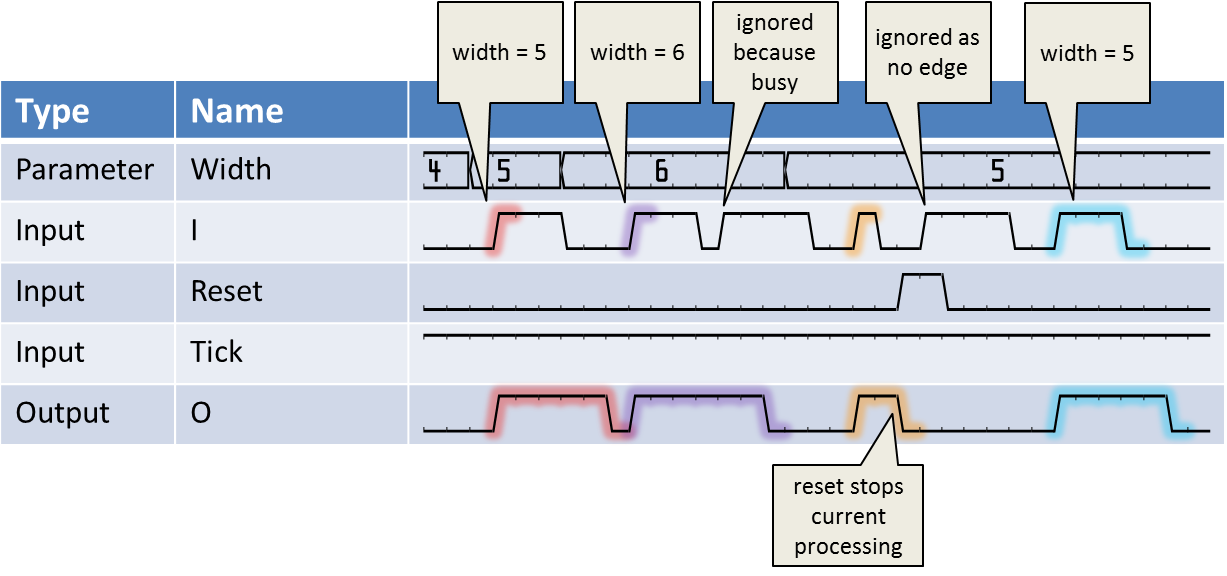
Via the input link Reset the user can reset the operator to its initial state.
The Tick input defines the time, the operator is processing data. It can be used like a prescaler. In most cases, the Tick input is not required. In this case, tie it to operator VCC. In the following figure, the influence of the Tick input is shown.
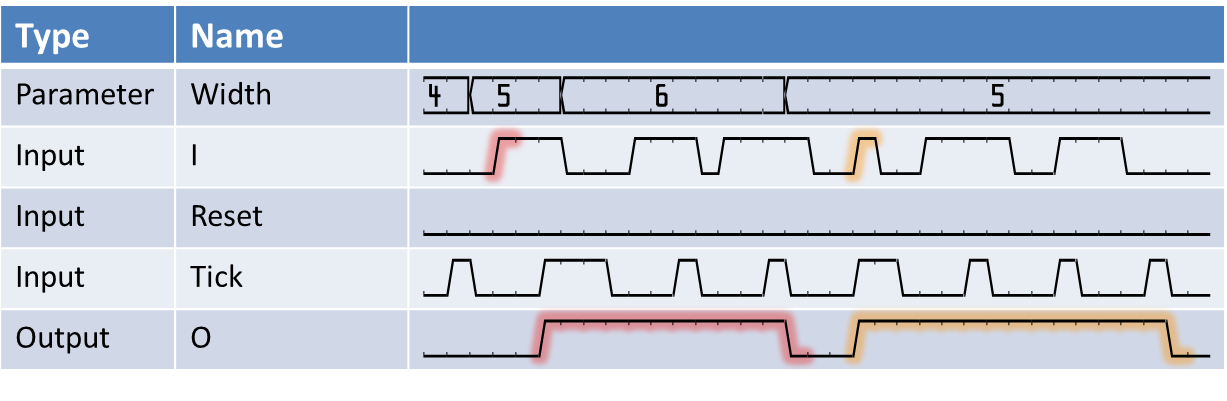
One special case when using ticks is that input pulses are sampled even if no tick is present. This is shown for the first input pulse of the waveform. This behavior ensures that no input pulses can get lost.
Pulses between two tick pulses are not lost (as long as it is only one pulse, i.e., as long as the pause between two incoming pulses is longer than a tick period). The operator recognizes the puls and starts interpretation of the puls as soon as the next tick is HIGH. Those small pulses are adapted to the tick time base and synchronized to the ticks. All changes at the operator output take place when tick is HIGH. Only if multiple input pulses come in between two occurences of tick = HIGH, the operator is unable to recognize them as different pulses as they are below the tick time base.
This operator is excluded from the VisualApplets functional simulation.
| Property | 值 |
|---|---|
| Operator Type | O |
| Input Links | I, signal input Tick, signal input Reset, signal input |
| Output Link | O, signal output |
| Link Parameter | Input Link I | Input Link Tick | Input Link Reset | Output Link O |
|---|---|---|---|---|
| Bit Width | 1 | 1 | 1 | as I |
| Arithmetic | unsigned | unsigned | unsigned | asI |
| Parallelism | 1 | 1 | 1 | as I |
| Kernel Columns | 1 | 1 | 1 | as I |
| Kernel Rows | 1 | 1 | 1 | as I |
| Img Protocol | VALT_SIGNAL | VALT_SIGNAL | VALT_SIGNAL | as I |
| Color Format | VAF_GRAY | VAF_GRAY | VAF_GRAY | as I |
| Color Flavor | FL_NONE | FL_NONE | FL_NONE | as I |
| Max. Img Width | any | any | any | as I |
| Max. Img Height | any | any | any | as I |
| WidthBits | |
|---|---|
| 键入 | static parameter |
| 默认 | 16 |
| 范围 | [1; 64] |
|
The maximum possible width is defined using this parameter. Stepsize is 1. This parameter is enabled only if Width is set to dynamic. If you reduce the value of paramter WidthBits so that the value of Width is bigger than the new maximal value, both parameters are displayed in red. The DRC shows an according error message. |
|
| Width | |
|---|---|
| 键入 | dynamic/static parameter |
| 默认 | 32768 |
| 范围 | [0;2^WidthBits-1] if dynamic, [0; 2^64-1] if static |
|
The actual output pulse width is defined using this parameter. Stepsize is 1 for dynamic and static. When width=0 there is no output. If set to dynamic, parameter WidthBits is activated. If set to static, parameter WidthBits is de-activated. If you reduce the value of paramter WidthBits so that the value of Width is bigger than the new maximal value, both parameters are displayed in red. The DRC shows an according error message. |
|
The use of operator SignalWidth is shown in the following examples:
-
Examples - Logic Analyzer: A comfortable way of oscilloscope like signal measurement and analysis.
-
Examples - Auto Exposure: Automatic ajustment of exposure time
-
'Area Scan Trigger for microEnable 5 marathon'
An area scan trigger is presented. External sources, an internal frequency generator or software trigger pulses can be used for trigger generation.
-
'Area Scan Trigger for microEnable 5 marathon VCX QP'
An area scan trigger for CoaXPress is presented. External sources, an internal frequency generator or software trigger pulses can be used for trigger generation.
-
'Area Scan Trigger for imaFlex CXP-12 Quad'
An area scan trigger for CoaXPress12 is presented. External sources, an internal frequency generator or software trigger pulses can be used for trigger generation.
-
'Line Scan Trigger for microEnable 5 marathon VCL Using Signal Operators and Operator CameraControl'
A line scan trigger is presented. The trigger includes an image trigger using a capture gate as well as a multi functional line trigger. External sources, an internal frequency generator or software trigger pulses can be used for trigger generation.
-
'Line Scan Trigger for microEnable 5 marathon VCX QP Using Signal Operators'
A line scan trigger is presented. The trigger includes an image trigger using a capture gate as well as a multi functional line trigger. External sources, an internal frequency generator or software trigger pulses can be used for trigger generation.
-
'Line Scan Trigger for imaFlex CXP-12 Quad Using Signal Operators'
A line scan trigger for CoaXPress12 is presented. The trigger includes an image trigger using a capture gate as well as a multi functional line trigger. External sources, an internal frequency generator or software trigger pulses can be used for trigger generation.
-
'Functional Example for Specific Operators of Library Signal'
Examples - Demonstration of how to use the operator
