Operator Library: Prototype
The TrgBoxLine operator generates the Exsync signal to control the exposure of a connected line scan camera. It also assembles the acquired lines into complete 2D images. Exsync is an external synchronization signal or an internally generated pulse with a fixed frequency that is sent to the line scan camera.
In a design, place this operator directly after the camera operator. The operator sends trigger signals to the camera to initiate line acquisition and receives the resulting image data on input link I. It then assembles the incoming lines into 2D images and outputs them on link O to subsequent operators.
The Exsync signal can be generated in two fundamental ways: periodically by the internal signal generator using the GrabberControlled mode, or triggered by external signals. External signals can originate from software as a software trigger or from peripheral devices via the slot bracket trigger port or a trigger expansion board with TTL or OPTO inputs. The operator's trigger signal generator can produce:
-
Exsync signals with configurable delay, pulse width, polarity, and
-
A secondary Exsync2 signal with an independent delay, and
- A Flash signal for synchronizing external devices.
The Flash output link is triggered by an external trigger input, e.g., the Image Gate. It has a configurable delay in line ticks and a pulse width of one line period. The Flash signal is useful for synchronizing additional frame grabber devices.
The operator provides eight trigger input ports and seven trigger output ports. Connect the input ports to the desired signal sources, e.g., a software trigger, a shaft encoder via trigger board pins, or to other frame grabbers via flatband cable. Connect the output ports to the required signal receivers, e.g., Exsync and Exsync2 for camera exposure control, Flash for synchronizing additional frame grabbers.
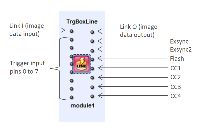
The camera control (CC) output ports can transmit Exsync, Exsync2, or Flash signals (including their inverted variants), or they can output static Vcc/GND levels. If you are not using a CC port, connect it to a Trash operator.
Some dynamic parameters cannot be modified while image acquisition is running. These parameters become available again once acquisition has stopped. In microDisplay X, the corresponding input fields are displayed as disabled during acquisition. When using the Framegrabber API, you must know which parameters are restricted during acquisition.
The following parameters cannot be changed during image acquisition:
- ImgTriggerMode
- MaxGatedHeight
- LineTriggerMode
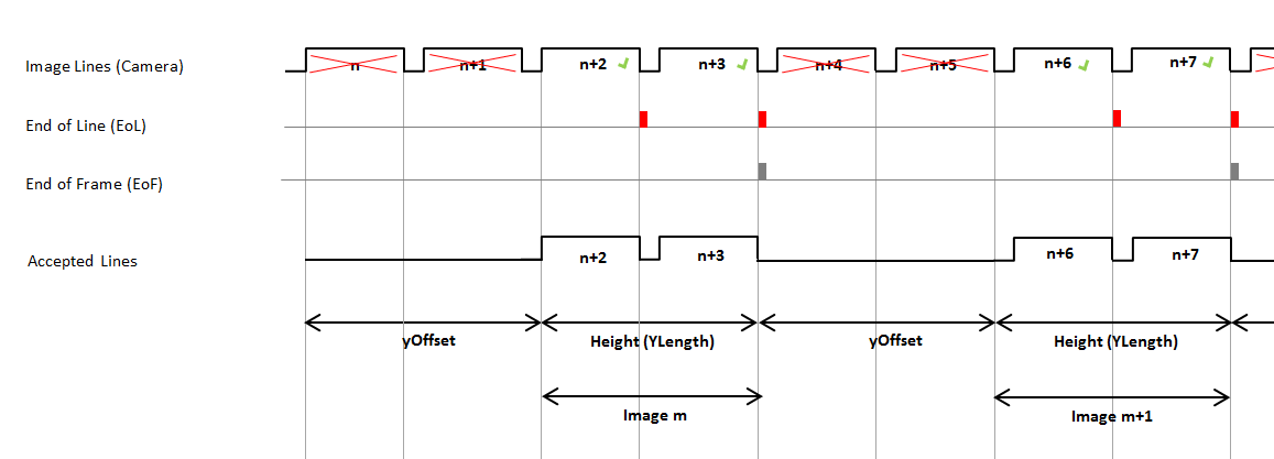
- YOffset
- YLength
| Property | 值 |
|---|---|
| Operator Type | M |
| Input Links | I, data input InSignal[n], n[0, 7], trigger input |
| Output Links | O, 2D image data output Exsync, Exsync signal for line scan camera exposure control Exsync2, Exsync 2 signal with specific delay for line scan camera exposure control Flash, Flash signal for additional frame grabber synchronization CC[n], n[1, 4], Multi purpose camera control signals with variable content: Exsync, Exsync2, Flash, Vcc or Gnd. |
| Link Parameter | Input Link I | Input Link InSignal[n], n[0, 7] | Output Link O | Output Link Exsync | Output Link Exsync2 | Output Link Flash | Output Link CC[n], n[1, 4] |
|---|---|---|---|---|---|---|---|
| Bit Width | [1, 64] | [1] | as I | [1] | [1] | [1] | [1] |
| Arithmetic | {unsigned, signed} | {unsigned} | as I | {unsigned} | {unsigned} | {unsigned} | {unsigned} |
| Parallelism | any | 1 | as I | 1 | 1 | 1 | 1 |
| Kernel Columns | 1 | 1 | as I | 1 | 1 | 1 | 1 |
| Kernel Rows | 1 | 1 | as I | 1 | 1 | 1 | 1 |
| Img Protocol | VALT_LINE1D | VALT_SIGNAL | VALT_IMAGE2D | VALT_SIGNAL | VALT_SIGNAL | VALT_SIGNAL | VALT_SIGNAL |
| Color Format | any | VAF_GRAY | as I | VAF_GRAY | VAF_GRAY | VAF_GRAY | VAF_GRAY |
| Color Flavor | any | FL_NONE | as I | FL_NONE | FL_NONE | FL_NONE | FL_NONE |
| Max. Img Width | any | any | as I | any | any | any | any |
| Max. Img Height | 65536 | any | as I | any | any | any | any |
| YOffset | |
|---|---|
| 键入 | dynamic/static read/write parameter |
| 默认 | 0 |
| 范围 | [0, 224] |
|
This parameter defines the number of lines omitted at the beginning of a frame. |
|
| YLength | |
|---|---|
| 键入 | dynamic/static read/write parameter |
| 默认 | 1024 |
| 范围 | [8, 224] |
|
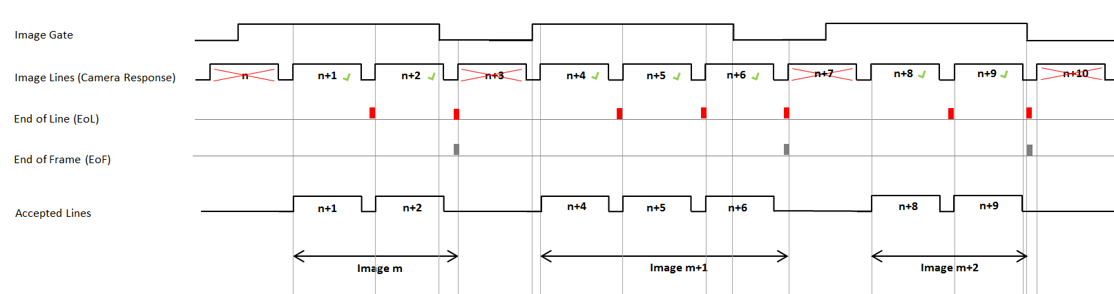
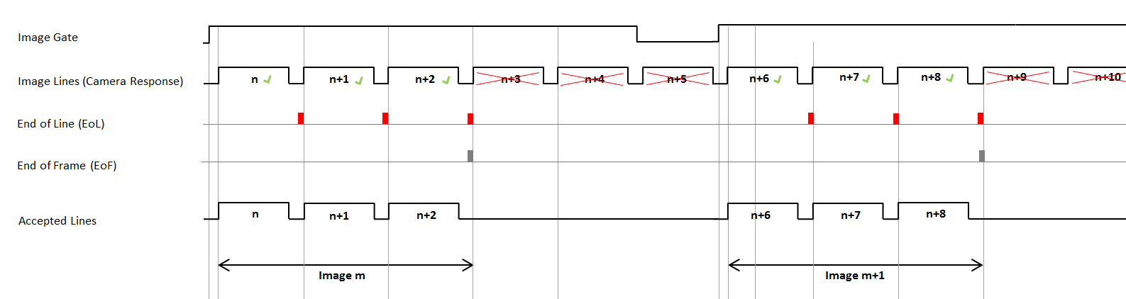
Specifies the number of lines per frame, i.e., the image height. If ImgTriggerMode is set to ExternSw_Gate and MaxGatedHeight is set to unrestricted, this parameter is ignored. In that case, the frame height is determined by the duration of the external Image Gate signal (see description of ImgTriggerMode). |
|
| MaxGatedHeight | ||||
|---|---|---|---|---|
| 键入 | dynamid read/write parameter | |||
| 默认 | restricted | |||
| 范围 | {restricted, unrestricted} | |||
|
Controls whether the maximum image height is limited when ImgTriggerMode is set to ExternSw_Gate. When set to restricted, the image height is limited to the value specified in YLength, even if the gate signal remains open. Any additional lines are discarded, and the operator waits for the next rising edge of the gate signal to start a new frame. When set to unrestricted, the image height is determined entirely by how long the gate remains open. In other words, it depends on the pulse width of the external image trigger signal or on how long the software trigger is held at value 1. If the gate stays open for an extended period, the resulting image can become very large.
|
||||
![[Note]](../common/images/admon/note.png)
| LineTriggerMode | |
|---|---|
| 键入 | dynamic/static read/write parameter |
| 默认 | GrabberControlled |
| 范围 | {GrabberControlled, Extern_Trigger, GrabberControlled_Gated_by_Img, Extern_Trigger_Gated_by_Img} |
|
Selects the operating mode for the internal Exsync signal generator. When using an external trigger mode, the trigger source is defined by LineTrgInSourceA and LineTrgInSourceB.
|
|
| ExsyncEnable | |
|---|---|
| 键入 | dynamic read/write parameter |
| 默认 | OFF |
| 范围 | {OFF, ON} |
|
Enables or disables the Exsync output to the camera. |
|
| LineTrgInSourceA | |
|---|---|
| 键入 | dynamic/static read/write parameter |
| 默认 | InSignal0 |
| 范围 | {InSignal0, InSignal1, InSignal2, InSignal3, InSignal4, InSignal5, InSignal6, InSignal7} |
|
This parameter specifies the signal source that is used to trigger the Exsync signal generator. This parameter is only relevant when LineTriggerMode is set to Extern_Trigger or Extern_Trigger_Gated_by_Img. |
|
| LineTrgInSourceB | |
|---|---|
| 键入 | dynamic/static read/write parameter |
| 默认 | InSignal0 |
| 范围 | {InSignal0, InSignal1, InSignal2, InSignal3, InSignal4, InSignal5, InSignal6, InSignal7} |
|
This parameter specifies the signal source which is used to trigger the Exsync signal generator. This parameter is only relevant when EncoderABMode is set to one of the A/B modes (Signal_AB_Filter, Signal_ABx2_Filter, or Signal_ABx4_Filter), and additionally:
|
|
| EncoderABMode | |
|---|---|
| 键入 | dynamic/static read/write parameter |
| 默认 | Signal_A_Only |
| 范围 | {Signal_A_Only, Signal_AB_Filter, Signal_ABx2_Filter, Signal_ABx4_Filter} |
|
Selects whether only trigger input A or both trigger inputs A and B are used for Exsync generation. 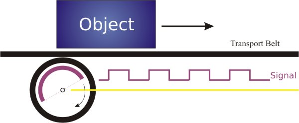 Signal A/B support lets the operator determine the rotation direction of the shaft encoder and either suppress backward movement or compensate for it: 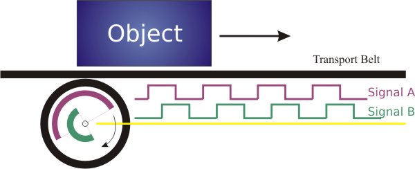
Related parameters when A/B support is enabled:
To reset the shaft encoder state and EncoderCompensationCount, set EncoderABMode to Signal_A_Only. |
|
| EncoderABLead | |
|---|---|
| 键入 | dynamic/static read/write parameter |
| 默认 | Signal_AB |
| 范围 | {Signal_AB, Signal_BA} |
|
Defines which signal leads to identify the forward rotation direction of the shaft encoder:
|
|
| EncoderCompensation | |
|---|---|
| 键入 | dynamic/static write parameter |
| 默认 | 开启 |
| 范围 | {ON/OFF} |
|
With parameter EncoderCompensation you can switch the compensation of the shaft encoder backward movement to ON or OFF. This parameter is only relevant, if the EncoderABMode parameter is set to A/B support. 开启 If set to ON, the operator monitors backward movement of the shaft encoder. When backward movement occurs, the operator counts how many encoder steps move in the backward direction. As soon as the shaft encoder moves forward again, these counted steps (now in the forward direction) are not transmitted as external trigger signals. Only after the transportation belt has returned to the position where the backward movement began are forward encoder steps transmitted as external trigger signals again. Parameter EncoderCompensation = ON: 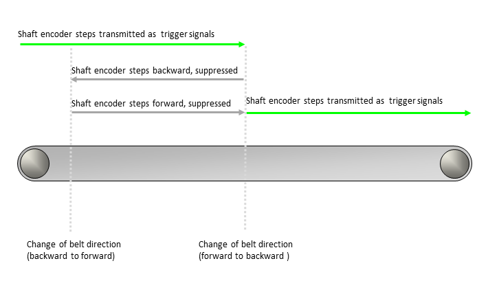
OFF If set to OFF, the operator does not transmit any trigger signals while the transportation belt is moving backward. As soon as the belt starts moving forward again, the operator resumes transmitting shaft‑encoder steps (in the forward direction) as trigger signals. Parameter EncoderCompensation = OFF: 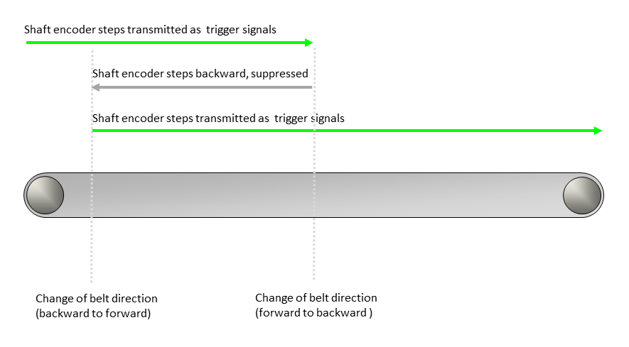
To reset the EncoderCompensationCount parameter to the value 0, set the EncoderCompensation parameter to OFF. |
|
| EncoderCompensationCountBits | |
|---|---|
| 键入 | static write parameter |
| 默认 | 20 bit |
| 范围 | {8 bit ... 31 bit} |
|
This parameter specifies the range of values that can be assigned to EncoderCompensationCount. |
|
| EncoderCompensationCount | |
|---|---|
| 键入 | dynamic read/write parameter |
| 默认 | 220 -1 |
| 范围 | {0 ... 2EncoderCompensationCountBits -1} (unit: shaft encoder steps) |
|
This parameter is only relevant, if the EncoderCompensation parameter is set to ON and the EncoderABMode parameter is set to A/B support. This parameter specifies an offset for the forward movement of the transportation belt. This is especially helpful, if the transportation belt stops and/or moves backwards. You can define a specific value range for the EncoderCompensationCount parameter with the EncoderCompensationCountBits parameter. To reset the shaft encoder and the EncoderCompensationCount parameter, set the EncoderABMode parameter to the Signal_A_Only value. Alternatively, you can reset the EncoderCompensationCount parameter to the 0 value by setting parameter EncoderCompensation to OFF. Basic Conditions If the EncoderCompensation parameter is set to ON, an internal counter counts the shaft encoder steps the transportation belt moves backwards. You can then compensate the exact number of shaft encoder steps when the transportation belt starts moving forwards again: 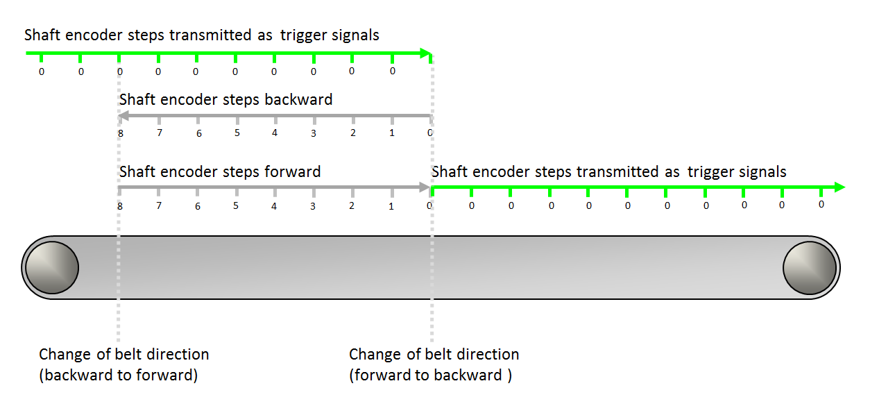
The internal counter counts forward as long as the transportation belt moves backwards. In the figure above: from 0 to 8. The internal counter counts backwards while the transportation belt moves forwards. In the figure above: from 8 to 0. When the internal counter holds the value 0, the shaft encoder steps are transmitted as trigger signals. The value the internal counter holds at a given moment is the value of the EncoderCompensationCount parameter. Only if this value is 0, encoder steps are transmitted as trigger signals. If the value of the EncoderCompensationCount parameter is ≠0, the shaft encoder steps are not transmitted as trigger signals and the value keeps changing with every encoder step until it reaches the value 0 again. Reading the Parameter The EncoderCompensationCount parameter is a read/write parameter. Therefore, you can read out the value the counter holds at any given moment. Defining an Offset On the other hand, you can always modify the parameter value since you have write access during acquisition. If you need to define an offset to the standard encoder compensation, you can use this parameter to enter the number of steps you need the offset to be. As soon as you enter a value for EncoderCompensationCount, this value overwrites the value the parameter held before. The following examples show how to modify the existing value of EncoderCompensationCount: Example 1: The transportation belt is moving forward, the shaft encoder steps are transmitted as trigger signals, and the value of EncoderCompensationCount is 0. Then, the value 0 of EncoderCompensationCount is overwritten by value 4. Result: 4 shaft encoder steps are not transmitted as trigger signals. 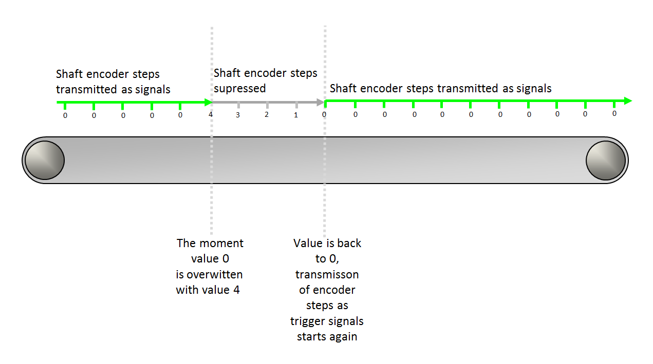
Example 2: The transportation belt is moving backward, the (backward) shaft encoder steps are suppressed, and the value of EncoderCompensationCount is ≠0. Then, during backward movement of the transportation belt, the value 5 of EncoderCompensationCount is overwritten by value 7. Result: Offset of 2 shaft encoder steps. 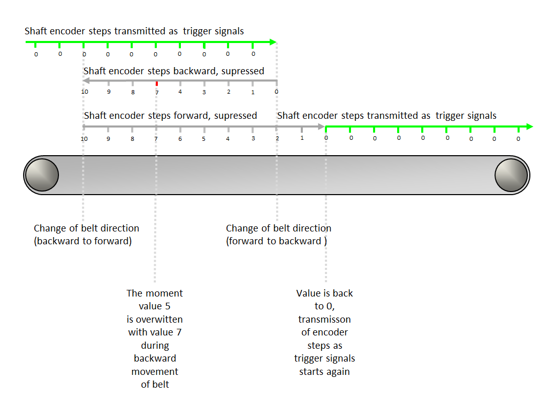
Example 3: The transportation belt is moving forward during compensation, the (forward) shaft encoder steps are suppressed, and the value of EncoderCompensationCount is ≠0. Then, during compensative forward movement of the transportation belt, the value 4 of EncoderCompensationCount is overwritten with value 9. Result: Offset of 5 shaft encoder steps. 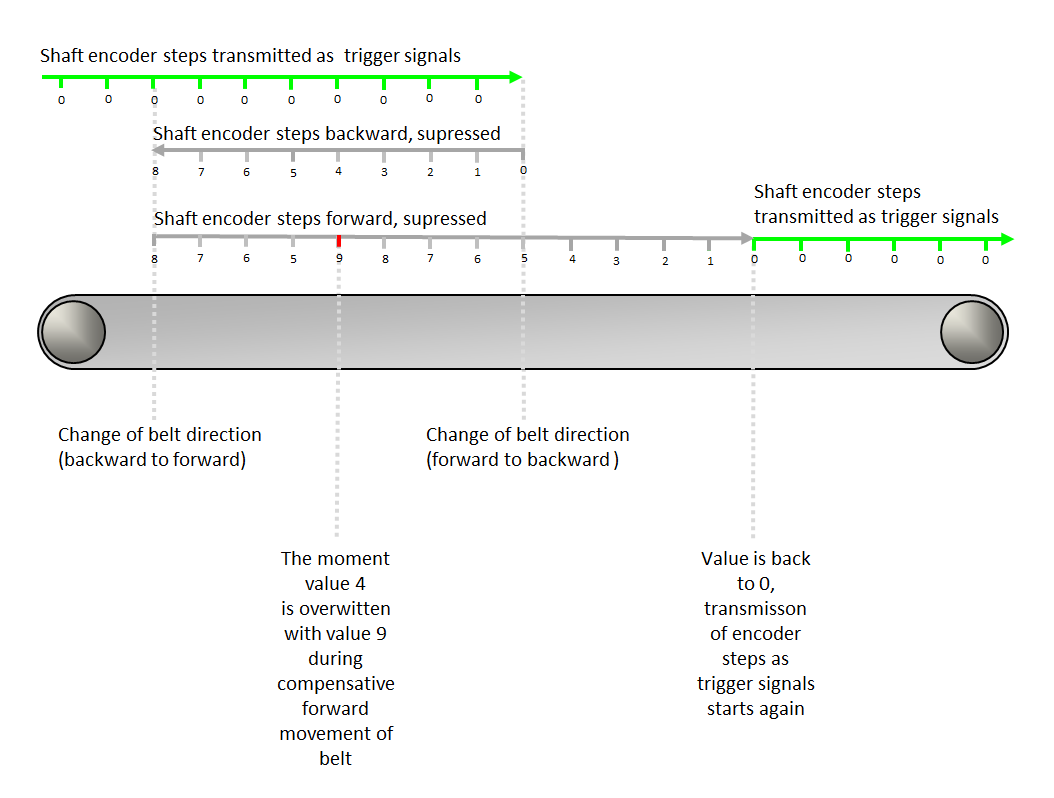
Example 4: The transportation belt is moving forward during compensation, the (forward) shaft encoder steps are suppressed, and the value of EncoderCompensationCount is ≠0. Then, during compensative forward movement of the transportation belt, the value 4 of EncoderCompensationCount is overwritten with a smaller value, in our case with value 3. Result: Negative offset of -1 shaft encoder steps. 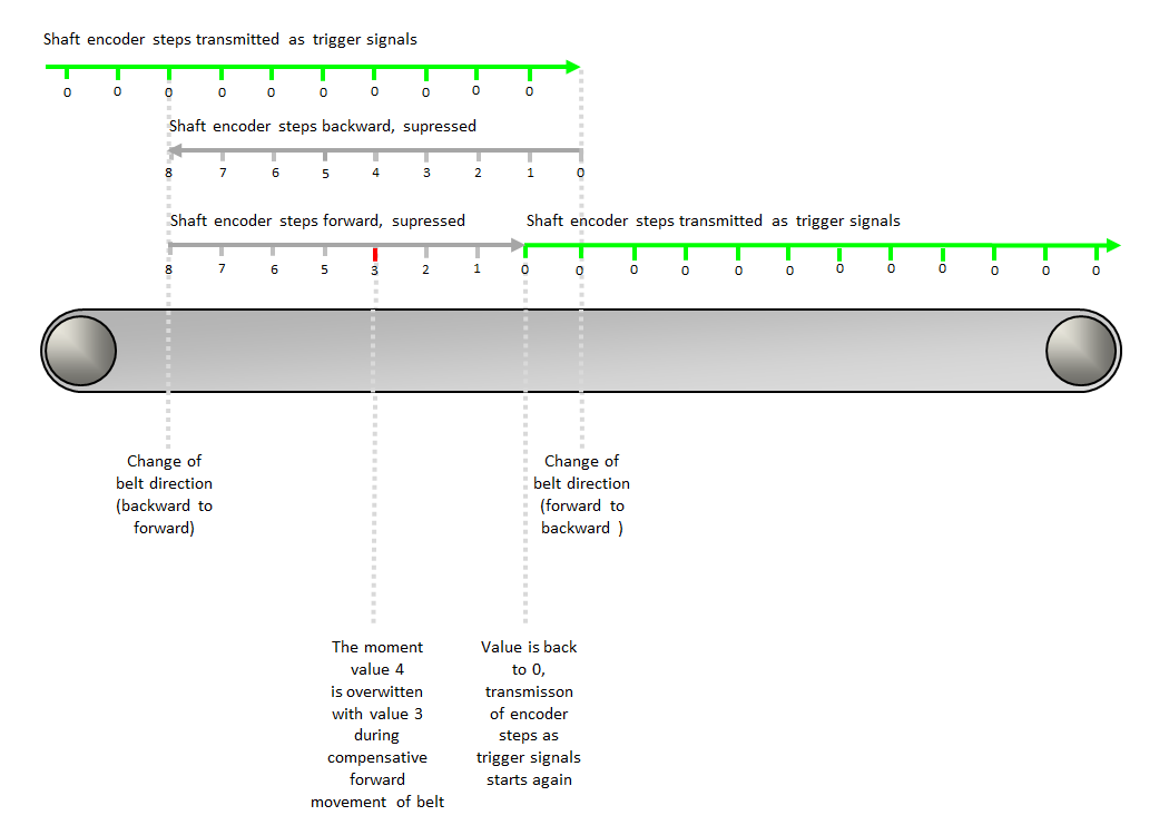
|
|
| LineTrgInPolarity | |
|---|---|
| 键入 | dynamic read/write parameter |
| 默认 | LowActive |
| 范围 | {LowActive, HighActive} |
|
The parameter defines the polarity of the external input trigger signals LineTrgInSourceA and LineTrgInSourceB. When set to LowActive, the Exsync generator starts on a falling edge of the specified line trigger source (LineTrgInSourceA / LineTrgInSourceB). Otherwise, the Exsync generation starts on a rising edge. This parameter is only relevant, if the LineTriggerMode is set to Extern_Trigger or Extern_Trigger_Gated_by_Img. |
|
| LineTrgDownscaler | |
|---|---|
| 键入 | dynamic/static read/write parameter |
| 默认 | 1 |
| 范围 | [1, 256] |
|
This parameter specifies the number of external input trigger signals that are needed to generate the Exsync. This parameter is only relevant, if the LineTriggerMode is set to an external trigger mode. |
|
| LineTrgPhase | |
|---|---|
| 键入 | dynamic/static read/write parameter |
| 默认 | 1 |
| 范围 | [1, 256] |
|
This parameter specifies the number of external input trigger signals that are needed to generate the first Exsync of a frame. This parameter is only relevant, if the LineTriggerMode is set to Extern_Trigger_Gated_by_Img. |
|
| ExsyncPeriod | |
|---|---|
| 键入 | dynamic/static read/write parameter |
| 默认 | 100 μs |
| 范围 | [64/DesignClockFrequencyInMhz, (218-1)/DesignClockFrequencyInMhz] µs |
|
This parameter specifies the period of the Exsync signal. Therefore, it defines the line frequency when using the grabber controlled mode to trigger the connected camera. This parameter's range and allowed step size depend on the FPGA clock frequency configured in the design. The allowed step size is 1/DesignClockFrequencyInMhz. DesignClockFrequencyInMhz = FPGA clock frequency in the design in MHz. |
|
| ExsyncExposure | |
|---|---|
| 键入 | dynamic/static read/write parameter |
| 默认 | 20 μs |
| 范围 | [64/DesignClockFrequencyInMhz, (217-1)/DesignClockFrequencyInMhz] μs, must not exceed ExsyncPeriod |
|
This parameter specifies the pulse width of the Exsync signal, which can be used by many cameras to specify the exposure time. Therefore, it is possible to adjust the exposure time via software, even while grabbing. This parameter's range and allowed step size depend on the FPGA clock frequency configured in the design. The allowed step size is 1/DesignClockFrequencyInMhz. DesignClockFrequencyInMhz = FPGA clock frequency in the design in MHz. |
|
| Exsync2Delay | |
|---|---|
| 键入 | dynamic/static read/write parameter |
| 默认 | 0 μs |
| 范围 | [0, (218-1)/DesignClockFrequencyInMhz] μs, must not exceed ExsyncPeriod |
|
This parameter specifies the delay of the generated Exsync signal with respect to an external trigger input. Therefore, the Exsync2 signal is a delayed clone of the Exsync: polarity, period, etc. are the same as for Exsync. This parameter's range and allowed step size depend on the FPGA clock frequency configured in the design. The allowed step size is 1/DesignClockFrequencyInMhz. DesignClockFrequencyInMhz = FPGA clock frequency in the design in MHz. |
|
| ExsyncPolarity | |
|---|---|
| 键入 | dynamic/static read/write parameter |
| 默认 | LowActive |
| 范围 | {LowActive, HighActive} |
|
This parameter adjusts the polarity of the Exsync signal generator to the polarity accepted by the connected camera. Use LowActive, if the camera opens the shutter on a falling edge, otherwise use HighActive. |
|
| ImgTriggerMode | |
|---|---|
| 键入 | dynamic/static read/write parameter |
| 默认 | FreeRun |
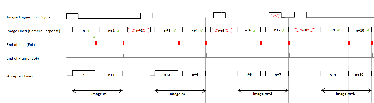
| 范围 | {FreeRun, ExternSw_Trigger, ExternSw_Gate} |
|
This parameter selects the operation mode for the internal Image Gate. The image trigger input signal may be created by external (i.e., peripheral) devices such as a shaft encoder, or by software. You can select the source for the external image trigger input via the ImgTrgInSource parameter, see below. The values of the ImgTriggerMode parameter induce the following behavior:
|
|
| ImgTrgInSource | |
|---|---|
| 键入 | dynamic/static read/write parameter |
| 默认 | InSignal0 |
| 范围 | {InSignal0, InSignal1, InSignal2, InSignal3, InSignal4, InSignal5, InSignal6, InSignal7, SoftwareTrigger} |
|
This parameter specifies the signal source which is used to trigger the image acquisition. This is only relevant, if the ImgTriggerMode is set to ExternSw_Trigger or ExternSw_Gate. |
|
| ImgTrgInPolarity | |
|---|---|
| 键入 | dynamic read/write parameter |
| 默认 | LowActive |
| 范围 | {LowActive, HighActive} |
|
This parameter defines the polarity of the external input trigger signal. |
|
| ImgTrgDelay | |
|---|---|
| 键入 | dynamic read/write parameter |
| 默认 | 0 |
| 范围 | {0, 65535} |
|
This parameter delays the image trigger signal by the given number of image lines. |
|
| FlashEnable | |
|---|---|
| 键入 | dynamic read/write parameter |
| 默认 | OFF |
| 范围 | {OFF, ON} |
|
Enables or disables the Flash output. The pulse width of the Flash signal is equal to one line period. |
|
| FlashPolarity | |
|---|---|
| 键入 | dynamic/static read/write parameter |
| 默认 | LowActive |
| 范围 | {LowActive, HighActive} |
|
This parameter defines the polarity for the generated Flash signal. |
|
| FlashDelay | |
|---|---|
| 键入 | dynamic/static read/write parameter |
| 默认 | 0 |
| 范围 | {0, 4095} |
|
This parameter specifies the number of lines to delay the generated Flash signal, with respect to an external trigger input. Therefore, it is possible to synchronize the Flash to the external trigger input. The pulse width of the Flash signal is equal to one line period. |
|
| SoftwareTrgPulse | |
|---|---|
| 键入 | dynamic/static write parameter |
| 默认 | 1 |
| 范围 | {1} |
|
Setting this parameter to 1 will generate a software trigger. This is only relevant, if the ImgTriggerMode is set to an external trigger mode and ImgTrgInSource is set to SoftwareTrigger. |
|
| SoftwareTrgInput | |
|---|---|
| 键入 | dynamic/static write parameter |
| 默认 | 0 |
| 范围 | {0, 1} |
|
With this parameter, a software gate can be produced for the image trigger mode ExternSw_Gate. |
|
| ImgTrgIsBusy | |
|---|---|
| 键入 | dynamic/static read parameter |
| 默认 | 0 |
| 范围 | {0, 1} |
|
The ImgTrgIsBusy parameter indicates the busy state of the image trigger. When the image trigger is busy, the parameter is set to 1 to indicate that an image is currently being captured. When it is set to 0, the image trigger is not busy. |
|
| CC1output | |
|---|---|
| 键入 | dynamic/static write parameter |
| 默认 | Exsync |
| 范围 | {Exsync, ExsyncInvert, Exsync2, Exsync2Invert, Flash, FlashInvert, Gnd, Vcc} |
|
This parameter specifies the signal available at the CC1 line (camera control 1). |
|
| CC2output | |
|---|---|
| 键入 | dynamic/static write parameter |
| 默认 | Exsync |
| 范围 | {Exsync, ExsyncInvert, Exsync2, Exsync2Invert, Flash, FlashInvert, Gnd, Vcc} |
|
This parameter specifies the signal available at the CC2 line (camera control 2). |
|
| CC3output | |
|---|---|
| 键入 | dynamic/static write parameter |
| 默认 | Exsync |
| 范围 | {Exsync, ExsyncInvert, Exsync2, Exsync2Invert, Flash, FlashInvert, Gnd, Vcc} |
|
This parameter specifies the signal available at the CC3 line (camera control 3). |
|
| CC4output | |
|---|---|
| 键入 | dynamic/static write parameter |
| 默认 | Exsync |
| 范围 | {Exsync, ExsyncInvert, Exsync2, Exsync2Invert, Flash, FlashInvert, Gnd, Vcc} |
|
This parameter specifies the signal available at the CC4 line (camera control 4). |
|
| ImgTrgDebouncingMaxTime | |
|---|---|
| 键入 | static write parameter |
| 默认 | 65.520 µs |
| 范围 | [1/DesignClockFrequencyInMhz, 1000000] µs |
|
This parameter defines the maximum value for the ImgTrgDebouncingTime parameter. A smaller maximum value reduces the FPGA resources required to implement the debouncing timer. The valid range and the permitted step size for this parameter depend on the FPGA clock frequency configured in the design. The permitted step size is 1 / DesignClockFrequencyInMhz. DesignClockFrequencyInMhz = FPGA clock frequency in the design in MHz. |
|
| ImgTrgDebouncingTime | |
|---|---|
| 键入 | dynamic/static write parameter |
| 默认 | 7/DesignClockFrequencyInMhz µs |
| 范围 | [1/DesignClockFrequencyInMhz, ImgTrgDebouncingMaxTime] µs |
|
This parameter specifies the debouncing time during which the input image trigger signal must remain unchanged to be recognized as valid. Fast signal changes within the debounce time will be filtered out. The valid range and the permitted step size for this parameter depend on the FPGA clock frequency configured in the design. The permitted step size is 1 / DesignClockFrequencyInMhz. DesignClockFrequencyInMhz = FPGA clock frequency in the design in MHz. |
|
| LineTrgDebouncingMaxTime | |
|---|---|
| 键入 | static write parameter |
| 默认 | 65.520 µs |
| 范围 | [1/DesignClockFrequencyInMhz, 1000000] µs |
|
This parameter specifies the maximum time for the LineTrgDebouncingTime parameter. A smaller maximum value reduces the FPGA resources required to implement the debouncing timer. The valid range and the permitted step size for this parameter depend on the FPGA clock frequency configured in the design. The permitted step size is 1 / DesignClockFrequencyInMhz. DesignClockFrequencyInMhz = FPGA clock frequency in the design in MHz. |
|
| LineTrgDebouncingTime | |
|---|---|
| 键入 | dynamic/static write parameter |
| 默认 | 7/DesignClockFrequencyInMhz µs |
| 范围 | [1/DesignClockFrequencyInMhz, LineTrgDebouncingMaxTime] µs |
|
This parameter specifies the debouncing time during which the input line trigger signal must remain unchanged to be recognized as valid. Fast signal changes within the debounce time will be filtered out. The valid range and the permitted step size for this parameter depend on the FPGA clock frequency configured in the design. The permitted step size is 1 / DesignClockFrequencyInMhz. DesignClockFrequencyInMhz = FPGA clock frequency in the design in MHz. |
|
The use of operator TrgBoxLine is shown in the following examples:
-
' Line Scan Trigger for microEnable 5 marathon VCL with TrgBoxLine Operator Usage'
A VisualApplets design example showing the usage of operator TrgBoxLine in a simple design.
-
'Line Scan Trigger for microEnable 5 marathon VCX QP with TrgBoxLine Operator Usage'
A VisualApplets design example showing the usage of operator TrgBoxLine in a simple design.
-
'Line Scan Trigger for imaFlex CXP-12 Quad with TrgBoxLine Operator Usage'
A VisualApplets design example showing the usage of operator TrgBoxLine in a simple design.
