Operator Library: Signal
The operator delays the input signal and provides it on its output. The delay is controlled by the control data input link PI.
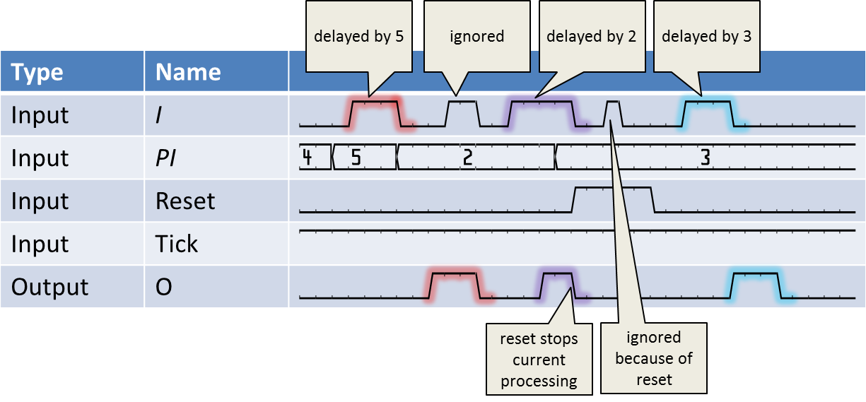
The rising edge of a pulse at the input starts the delay. The delay time is equal to the last valid value at input link PI and is measured in ticks being high. The pulse width of the input pulse is kept, i.e. the rising and falling edges are delayed.
During delaying of a pulse no new pulses at the operator input can be accepted. In this case, every new input pulse will be ignored. Moreover, a change of the value at PI does not change the current pulse processing. PI is sampled at the start of the delay.
The operator can be reseted using input link Reset. While the reset input is high, no output pulses are processed. Any processing is aborted. The operator restarts operation when the reset input is low. The following waveform illustrates the operator's behavior.

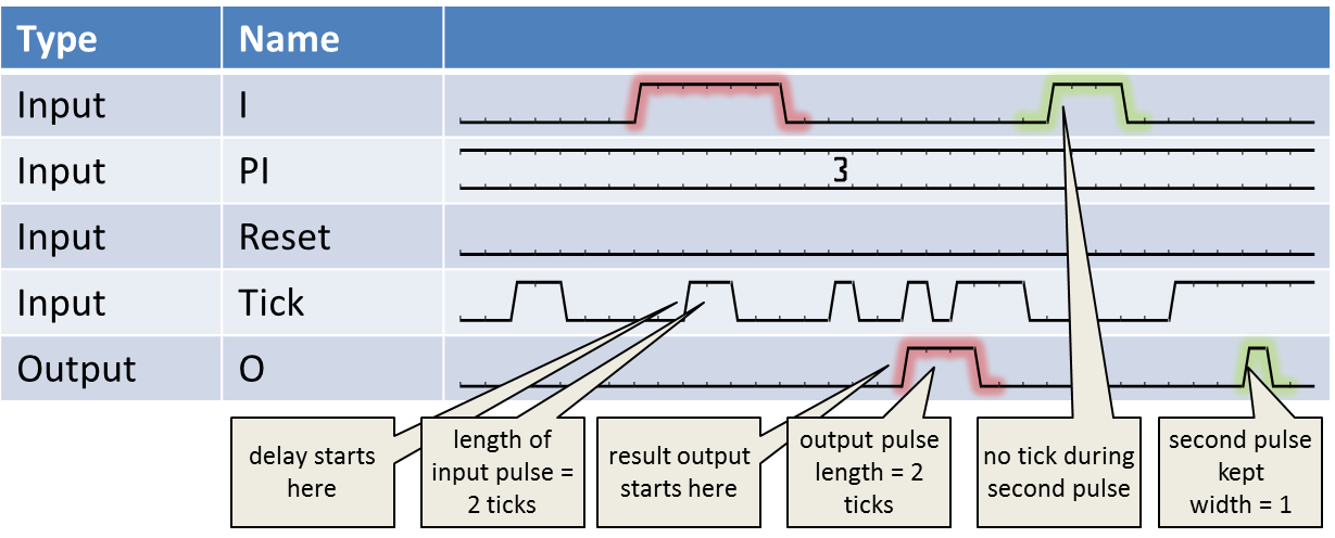
The Tick input defines the time, the operator is processing data. It can be used like a prescaler. In most cases, the Tick input is not required. Tie it to operator VCC in this case. In the following figure, the influence of the Tick input is shown.

One special case when using ticks is that input pulses are sampled even if no tick is present. This is shown for the second input pulse of the waveform. This ensures that no input pulses can get lost.
This operator is excluded from the VisualApplets functional simulation.
| Property | Value |
|---|---|
| Operator Type | O |
| Input Links | I, signal data input PI, control image data input Tick, signal data input Reset, signal data input |
| Output Link | O, signal data output |
Synchronous and Asynchronous Inputs
- All signal inputs may be sourced by the same or different M-type operators through an arbitrary network of O-type operators. If they are sourced by the same M-type source, they will be automatically synchronized.
- Input link PI is asynchronous to the signal inputs.
| Link Parameter | Input Link I | Input Link PI | Input Link Tick | Input Link Reset | Output Link O |
|---|---|---|---|---|---|
| Bit Width | 1 | [1, 64] | 1 | 1 | as I |
| Arithmetic | unsigned | unsigned | unsigned | unsigned | as I |
| Parallelism | 1 | 1 | 1 | 1 | as I |
| Kernel Columns | 1 | 1 | 1 | 1 | as I |
| Kernel Rows | 1 | 1 | 1 | 1 | as I |
| Img Protocol | VALT_SIGNAL | {VALT_IMAGE2D, VALT_LINE1D, VALT_PIXEL0D} | VALT_SIGNAL | VALT_SIGNAL | as I |
| Color Format | VAF_GRAY | VAF_GRAY | VAF_GRAY | VAF_GRAY | as I |
| Color Flavor | FL_NONE | FL_NONE | FL_NONE | FL_NONE | as I |
| Max. Img Width | any | any | any | any | as I |
| Max. Img Height | any | any | any | any | as I |
The use of operator DelayToSignal is shown in the following examples:
-
'Functional Example for Specific Operators of Library Signal, Logic, Filter and Parameters'
Examples - Demonstration of how to use the operator

 Prev
Prev

