Any diagram created in VisualApplets is a network of operator instances (modules). It may combine several sub-networks.
Like other programming languages, the diagrams you create in VisualApplets are subject to a set of rules with allowed, not allowed, and limited constructs. The following sections define the basic rules of connecting modules.
At first, let us have a look at the different types of operators you are working with.
In VisualApplets, you have three types of operators:
| The universal type “O” (round shape): |

|

|
|
| The more complex type “M” (square shape): |

|
In older versions of VisualApplets and some examples in documentation oval shape: |

|
| The special type “P” (square shape): |

|
In older versions of VisualApplets and some examples in documentation oval shape: |

|
Table 4. Operator Types
You can see by the shape of an operator if it belongs to the universal “O” type or to one of the more complex “M” or “P” types. (For information on the type of a specific operator, check the documentation for that operator in Operator Reference.)
The functionality of O-type operators is rather simple. Therefore,
-
O-type operators do not change the number of pixels/data between input and output. The number of input pixels/data of all input links is equal to the number of output pixels/data, i.e. for each input value, the operator will output a value.
-
O-type operators do not add a delay between input and output.
-
O-type operators can be linked as desired in series or in parallel.
The functionality of M-type operators is more complex:
-
They can change the number of pixels/data between input and output.
-
They may delay the output.
-
Linking of M-type operators requires attention to the rules of links and to the functionality of the linked operators.
-
M-type operators may block the input.
-
Every source operator in a diagram (such as e.g. CameraGrayAreaBase) is an M-type operator.
-
Every final-destination operator in a diagram (such as e.g. DmaToPC) is an M-type operator.
P-type operators are similar to M-type operators, but
-
P-type operators do not reduce the bandwidth. (For more information on this issue, see 'Infinite Sources / Connecting Cameras'.)
-
P-type operators will not generate more data than given at the input(s).
-
P-type operators never block the input actively. (See 'P-Type Operators' for detailed information on the blocking behavior of P-type operators.)
In the following, all rules defined for M-type operators also apply for P-type operators if no exception for P-type operators is mentioned.
An O-type network is a combination of O-type modules. In an O-type network, modules may be combined in series as well as in parallel. An O-type network always starts and ends with M-type or P-type modules. On the basis of this definition, an important rule can be defined:
![[Tip]](../common/images/admon/tip.png) |
O-Type Network Rule |
|---|---|
|
In an O-type Network, no matter how complex it might be, each O-type module has to be sourced by the same M-type or P-type module. It may be connected to this source via other O-type modules or even O-type (sub)networks. (Please note that this rule does not apply to signal links.) |
The following figure shows an O-type network including parallel and serial connection of modules. As you see, all O-type modules are sourced by the same M-type module (M_source).
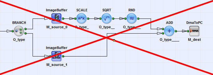
In contrast, the next figure shows an O-type network which violates the O-Type Network Rule as the ADD module is sourced by different M-type modules (M_source_0 and M_source_1).
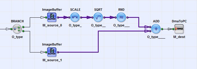
VisualApplets (version 2.2 and higher) reliably indicates directly in the design diagram whenever a synchronization rule is violated. The respective links are highlighted in purple. The links are highlighted from the operator that receives not correctly synchronized data back to the according M operator sources.
DRC 1 and DRC 2 display according warnings.
For example, for the above design, DRC 1 creates the following warning:

![[Important]](../common/images/admon/important.png) |
Exception: Signal Links |
|---|---|
|
The O-type network rule does not apply for O-type operators transporting signal links (see 'Differing Rules for Signal Links'). |
Any network of modules that contains M-type modules not only as source and destination, but also in between for image processing purposes, is called an M-type network. In M-type networks, M-type modules can be linked in parallel as well as in series. M-type modules can also be branched without limitations. M-type networks may turn out pretty complex, as parallel linking of M-type modules may demand synchronization of image dimensions and synchronization of timing. (Remember: M-type modules can change the number of pixels/data between input and output; they also may delay the output.)
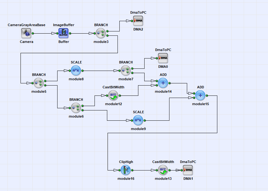
The following figure shows a very simple example of an M-type network. The M-type modules of this diagram are only connected in series, or branched. Since the only O-type network in the diagram is sourced by the same M-type module (ImageBuffer), the diagram follows all diagram rules we know so far:
In most cases, M-type networks are much more complex. If, in contrast to the example above, M-type modules are linked in parallel (i.e., the merging paths are sourced by different M-type sources), we have to synchronize the timing and the image dimensions. This is done by M-type operators using multiple inputs.
If you want to merge networks sourced by different M-type sources, you have to use M-type operators with multiple inputs. (You can't use O-type operators with multiple inputs as this would violate the rules for O-type networks as described above.) But before going into detail on synchronization, let's have a look at M-type operators with multiple inputs in general.
M-type operators with multiple inputs can have two kinds of inputs:
-
Synchronous inputs
-
Asynchronous inputs
Synchronous Inputs and Synchronous-Input Groups
If some inputs of a module are synchronous, these synchronous inputs form together one synchronous-input group. Thus, an synchronous-input group is a set of synchronous inputs. The inputs of an synchronous-input group always have to be sourced by the same M-type source through an arbitrary network of O-type operators. An M-type operator can have an arbitrary number of synchronous-input groups.
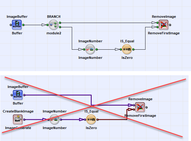
On the picture below, you see an example of the use of an M-type operator with a synchronous-input group. Both inputs of the RemoveImage operator are sourced by the same M-type operator (ImageBuffer). The two inputs together form the group of synchronous inputs. The operator RemoveImage does not allow to use different M-type sources at its input ports.
Asynchronous Inputs
Asynchronous inputs are not synchronous. They may be sourced by different M-type operators through an arbitrary network of O-type operators. Moreover, some M-type operators with multiple inputs actually have to be sourced by different M-type operators. Whether an M-type operator with multiple inputs has to be sourced by different M-type operators or not depends on the features of the operator itself. You find detailed information on all operators in Operator Reference. An M-type operator can have an arbitrary number of asynchronous inputs.
The following screenshot shows a typical example of an M-type operator with two asynchronous inputs. Both inputs of the SYNC module are sourced by different M-type sources, namely DRAM0 and DRAM1.
The SYNC module is followed by a MergePixel operator. This operator can't be used to merge the two M-type sources without the SYNC operator in-between.
![[Important]](../common/images/admon/important.png) |
M-Type Operator Inputs |
|---|---|
|
The inputs of M-type modules may be sourced by different M-type sources. However, the inputs of a synchronous-input group have to be sourced by the same M-type source through an arbitrary network of O-type operators. |
The documentation for each M-type operator with multiple inputs explains the possible or required inputs for the operator in great detail. For a comprehensive description of all operators, see Operator Reference.
M-type operators may synchronize different image dimensions at their inputs. One important example is the operator SYNC. See Operator Reference for a detailed description of this operator.
For O-type networks, VisualApplets automatically performs timing synchronizations.
For M-type networks, the synchronization has to be carried out by M-type operators.
If a timing synchronization is not designed correctly,
-
a so called deadlock-condition will occur,
-
the bandwidth is not sufficient, or
-
data will get lost.
![[Warning]](../common/images/admon/warning.png) |
Ensure correct timing synchronization |
|---|---|
|
Since the timing synchronization depends on the behavior of the algorithm you implement in VisualApplets, you have to make sure the timing synchronization in your diagram is correct. |
In the following examples, we will have a closer look at timing synchronization.
-
Synchronization of Independent Sources
Let's have a look at a simple two-camera stitching example which is shown in Figure 59, 'Synchronization of Independent Sources'. In the example, two cameras are used as a source. The ImageBuffer operators will buffer the data. Finally, the M-type operator InsertLine will multiplex the lines of both cameras into one output link. This operator merges the two parallel links.
Imagine what happens if the two cameras are not synchronous. Suppose the frame rate of one camera is higher than the framerate of the other. The InsertLine operator will strictly multiplex the lines, i.e. will use the inputs one after another. Due to the different frame rates, one of the DRAM buffers will need to actually buffer data. Its fill level will be constantly increasing. As soon as an overflow condition occurs, no more data can be buffered, and data will get lost.
![[Important]](../common/images/admon/important.png)
Ensure Equal Data Rate Thus, if asynchronous streams are merged together, ensure that the line rate/frame rate/pixel rate is equal and can be synchronized.
-
Synchronization of Data from the Same Source
Some M-type operators create a delay until they can output their results. A prominent example is the operator FIRkernelNxM which is used in the diagram we explore in the following figures. This operator outputs a pixel together with its surrounding neighbors to form a kernel. To output the neighbored pixels, the operator has to wait until they (the required neighbored pixels) are available at the input. It will store the intermediate results. In our example, the FIRkernelNxM operator can output the first results only after four full lines have been fed into the operator. Thus, the operator generates a delay of four image lines in its current configuration.
Let's have a closer look at this example.
Precondition
The first pixels are send from a camera through the buffer into the branch. Here, data is duplicated and forwarded to the SYNC and FIRkernelNxM modules. As explained, the FIRkernelNxM has a delay of four lines and therefore is not able to output the first pixels immediately:
Deadlock
The SYNC operator tries to synchronize both inputs. As no data is coming from the second input, it generates a STOP-signal at the first input. This STOP-signal is propagated backwards in the pipeline up to the buffer. Now, we have the deadlock condition: The kernel operator requires more data until it is able to output data, but no new data are available because the SYNC blocks all further inputs.
Fixing the Deadlock
To solve the deadlock, we have to add a buffer to the upper path, so that the delay of the kernel operator can be compensated as shown in the following:
Avoiding the Deadlock
The best solution is to avoid synchronization at all. This is often possible. In the solution example below, there is only a serial pipeline of M-type operators in the diagram and therefore, no synchronization at the merge is required.
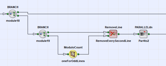
Another important phenomenon in M-type networks is the reduction of bandwidth in an operator together with a possible propagation of this limitation backwards in the network of modules. The following figure shows a diagram which will generate a bandwidth limitation.
In this diagram, the combination of ModuloCount and RemoveLine operator will delete every second line. As we know from 'Bandwidth of an Applet', the maximum bandwidth depends on the used parallelism. After the RemoveLine operator, the required bandwidth has been reduced by a factor of two. Therefore, we can reduce the parallelism by a factor of two using operator PARALLELdn ("Parallel down"). However, this will also reduce the bandwidth in the upper path by factor two for every second line.
While a line is deleted at the RemoveLine operator, no pixels are fed into the PARALLELdn module. The full parallelism as given at the input of the diagram can be used in both paths. In contrast, when a line is not removed by the RemoveLine operator, the pixels of the current line are forwarded to the input of the PARALLELdn. PARALLELdn will now reduce the parallelism by two, i.e., it requires the double number of cycles to output a value compared to the input. Thus, the PARALLELdn operator will block its input every second clock cycle. As no buffer is used between the first Branch and the PARALLELdn operator, this blocking signal is propagated backwards in the pipeline. Therefore, the upper path is blocked every second clock cycle, too.
A solution to this problem is to add an extra FIFO before the PARALLELdn operator which is able to buffer a minimum of one line and thus compensates the peak and idle periods. The following figure shows this solution:
P-type operators are similar to M-type operators, with one exception: They can not block the input actively.
Nevertheless, when a module further up the processing pipeline blocks its input, the input blocking is propagated backwards the line. If a P-type operator is positioned further down the line, the P-type operator`s input port gets blocked, too (passively). P-type operators propagate the blocking information backwards to the next module down the processing line.
Example: The M-type operator PARALLELdn requires more time to output the results compared to the time the data is fed into the operator. Therefore, it will block the input from time to time. In contrast, a P-type operator PARALLELup will always have a higher bandwidth at the output compared to the input bandwidth. This behavior is very important when connecting infinite sources with P-type and M-type operators. A detailed description of infinite sources is presented next in 'Infinite Sources / Connecting Cameras'.
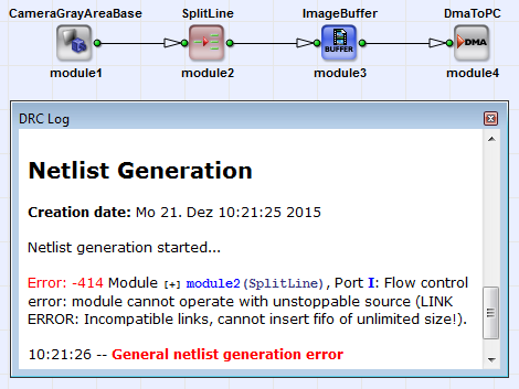
Infinite sources are operators which cannot be stopped by the VisualApplets flow control. One example are the camera operators. On their input link, these operators receive data from the camera. On their output link, they forward this data to the successive module in the diagram. As there is no buffer within the camera operators, and as they are not able to tell the cameras to stop the transfer, these operators are infinite sources.
Infinite sources can only be connected to M-type operators which accept infinite sources. Whether an individual M-type operator can be connected to an infinite source or not is described in the respective documentation for this operator (see Operator Reference). If an infinite source is connected to an M-type operator which does not accept infinite sources, the DRC level 2 will generate an error:
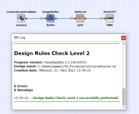
All P-type and O-type operators can be connected to infinite sources. The infinite source information will propagate through operators until an operator in the pipeline will convert the infinite source data stream into a controllable data stream. Usually, these conversion operators are buffers. A buffer operator is able to use the flow control at its output and buffers the input data stream without the need to block the input.
Thus, if we swap the operators of the previous example, the DRC level 2 will not generate an error:
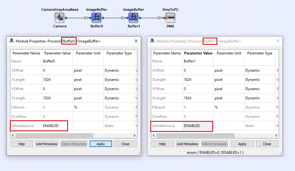
The behavior of some of the conversion operators can be changed to whether they accept infinite sources or not. These operators include a parameter called InfiniteSource which can be set to Enabled or Disabled.
A conversion operator which is not connected to an infinite source must be set to Disabled.
![[Warning]](../common/images/admon/warning.png) |
Warning |
|---|---|
|
If the parameter InfiniteSource of an respective module is set to Enabled, the module must be connected to an infinite source. A conversion operator which is not connected to an infinite source must be set to Disabled. |
![[Tip]](../common/images/admon/tip.png) |
Tip |
|---|---|
|
Always set the parameter to Disabled if you are not sure, and change the failing modules after the DRC level 2 check. |
For a detailed description of the parametrization of modules, see 'Module Properties'.
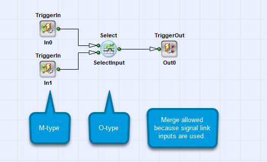
Signal links transport one-bit signal data which is valid at every clock cycle. The rules of links for modules with signal transporting input links differ in two ways from the rules of links described so far:
-
All O-type and M-type modules with signal link inputs may be sourced by different M-type sources.
-
Modules with signal link inputs may always be connected to infinite sources.
Find more information on signal links in 'Image Protocols, Image Dimensions and Data Structure'.
In this chapter you have been introduced to the rules of links. The rules of links are most important when implementing a VisualApplets application.
O-type networks always start and end with an M-type module. Each O-type module has to be sourced by the same M-type or P-type module through an arbitrary network of other O-type modules. Merges of different M-type sources can only be performed by M-type modules.
M-type networks may be arbitrarily linked in a serial sequence as well as they may be branched arbitrarily. Merging of different M-type sources in a module requires timing synchronization and image dimension synchronization. M-type modules with multiple inputs can have synchronous-input groups. Synchronous-input groups have to be sourced by the same M-type source through an arbitrary O-type network.
Timing synchronization will synchronize different sources which are timely delayed. Timing synchronization requires knowledge of the user implementation. A bad timing synchronization will result in deadlocks or buffer overflows.
An infinite source cannot be controlled by the integrated flow control. Only M-type operators which are allowed to be connected to infinite sources may be connected to infinite sources.
To modules with signal link inputs, the general synchronization rules apply with two modifications: The signal link inputs (of M-type and O-type modules) may be sourced by different M-type sources. Modules with signal link inputs may always be connected to infinite sources.
![[Warning]](../common/images/admon/warning.png) |
Warning |
|---|---|
|
VisualApplets cannot detect logic synchronization errors as they depend on the user project implementation. Read the documentation of each M-type operator carefully to learn about its behavior in timing and delay. |





 Prev
Prev

