Operator DFRxData

Operator Library: Hardware Platform

This operator represents a logical data reception link over a QSFP28 fiber port. The link uses specific fiber lanes within the selected port and receives data on output O from another frame grabber. The status of the RX PHY is provided on the output LinkUp.

The DFRxData operator can be used only if the FiberProtocol0 and FiberProtocol1 parameters in the AppletProperties operator are set to DataForwarding. If the FiberProtocol0 and FiberProtocol1 parameters in the AppletProperties operator are set to CoF, the Design Rules Check (DRC) provides an error message and the DFRxData operator usage is blocked.

The operator can use between 1 and 4 lanes within a QSFP28 port for data reception. This flexibility allows optimizing port usage for different scenarios. As a result, a single QSFP28 port can be shared by multiple DFRxData operators in the following configurations:

  • 1 x4 operator

  • 2 x2 operators

  • 1 x2 operator plus 2 x1 operators

  • 1 x3 operator plus 1 x1 operator

  • 4 x1 operators

A QSFP28 fiber port provides a total bandwidth of 100 Gbit/s, divided across four lanes. Each lane operates at 25 Gbit/s. Depending on the configuration, the operator runs at the following speeds:

  • x4 lanes: 100 Gbit/s

  • x3 lanes: 75 Gbit/s

  • x2 lanes: 50 Gbit/s

  • x1 lane: 25 Gbit/s

The operator can share its allocated lanes with the DFRxMeta operator without any conflict. However, lane sharing between multiple DFRxData operators is not allowed.

The DFRxData operator does not require a special protocol. It serves as the endpoint of a logical link between two frame grabbers: DFTxData (source, FG 1) and DFRxData (sink, FG 2). The link settings must be identical on both sides, including the QSFP28 port and lane configuration. Additionally, the VisualApplets link protocol must match on both ends. It is either VALT_IMAGE2D or VALT_IMAGE1D.

Data reception on the DFRxData operator can be paused by following operators. During a pause, no data is lost; the pause signal propagates to the sender, and the transmitter stops sending. When the blocking operator removes its inhibit on the DFRxData link, transmission resumes normally. The data pipeline includes buffers to handle temporary pauses:

  • RX side: Large buffer (1024 entries) to absorb short reception blockages without stopping transmission.

  • TX side: Small buffer (64 entries) to handle brief metadata transmissions without interrupting sending.

For more details about data forwarding, see 'Data Forwarding with imaFlex 2 Dual 100 Frame Grabbers'.

Available for Hardware Platform
imaFlex 2 Dual 100

Resources

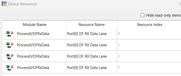
The operator mirrors the FiberConnection parameter setting into the FPGA Device Resources dialog as read-only parameters. You can see the FPGA device resources, if you open the FPGA Device Resources dialog from the Analysis menu. The device resources are read-only:

FPGA Device Resources

Figure 425. FPGA Device Resources


Depending on the allocated port, the resource is of the type Port[0] DF RX Data Lane or of the type Port[1] DF RX Data Lane with the index range from 0 to 3. The number of lanes allocated by the operator depends on its configuration:

  • x4: uses all 4 lanes of the QSFP28 port

  • x3: uses 3 lanes

  • x2: uses 2 lanes

  • x1: uses 1 lane

I/O Properties

Property Value
Operator Type M
Output Links O, image data output
LinkUp, indicates link status

Supported Link Format

Link Parameter Output Link O Output Link LinkUp
Bit Width 64 1
Arithmetic unsigned unsigned
Parallelism 1, 2, 3, or 41 1
Kernel Columns 1 1
Kernel Rows 1 1
Img Protocol {VALT_IMAGE2D, VALT_LINE1D} {VALT_SIGNAL}
Color Format VAF_GRAY VAF_GRAY
Color Flavor FL_NONE FL_NONE
Max. Img Width any (default: 16777216) This parameter is ignored during operation.
Max. Img Height any (default: 16777216) This parameter is ignored during operation.

The O link delivers the received data to VisualApplets. The LinkUp link indicates the connection status: When LinkUp is active, the paired TX side and the RX side are both ready to transmit and receive data, meaning the link is trained and operational.

1

The parallelism is determined by the FiberConnection parameter. It equals the number of fiber lanes in use.

Parameters

FiberConnection
Type Static Write parameter
Default port_0_lane_0_1_2_3
Range {port_0_lane_0_1_2_3, port_0_lane_0_1_2, port_0_lane_0_1, port_0_lane_2_3, port_0_lane_0, port_0_lane_1, port_0_lane_2, port_0_lane_3, port_1_lane_0_1_2_3, port_1_lane_0_1_2, port_1_lane_0_1, port_1_lane_2_3, port_1_lane_0, port_1_lane_1, port_1_lane_2, port_1_lane_3}

This parameter specifies the QSFP28 fiber port and lanes used by the DFRxData operator to receive data.

The selected QSFP28 port can be used only if the FiberProtocol parameter in the AppletProperties operator for that port is set to DataForwarding and not to CoF.

If FiberProtocol is set to CoF and the DFRxData operator attempts to map to that fiber port, the Design Rule Check (DRC) will generate an error message. In this case, the FiberConnection parameter will be marked as conflicted (red), and hovering over it will display a quick-tip help message explaining the conflict.

Only one DFRxData operator can use the same hardware QSFP28 port on the same lane. Mappings between multiple operators must be unique across the entire design.

Examples of Use

The use of operator DFRxData is shown in the following examples: