You define number and type of the interfaces of the VA IP core (as described 'Defining the IP Core Properties'.
However, two Interfaces are the same for all platforms: The clock interface and the register slave interface. These will be described here before you actually start to fill in your hardware description file.
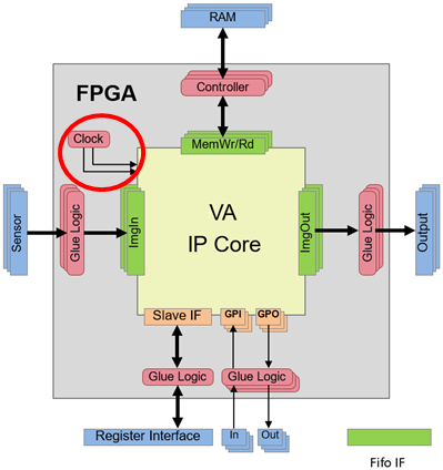
In hardware, you need to provide two clock inputs to the IP core: iDesignClk and iDesignClk2x. Such clock signals you can usually generate quite easily using a digital clock manager of the FPGA (under your control).
These clocks must hold following requirements:
-
Being phase synchronous
-
Having a frequency ratio of 2 where iDesignClk2x is the faster one.
Influence of clock input on design speed: All operators of a VisualApplets design work synchronous to the rising edge of iDesignClk.
During IP core definition in eVA Designer, you will set up an
allowed frequency range constraint for the IP core (i.e., for
iDesignClk) (as described in section 'Entering FPGA Details', step 3). This information is provided to VisualApplets.
During design with VisualApplets, the VisualApplets user selects a target frequency (for
iDesignClk) within the allowed range. This information will be used
for synthesis and implementation: After synthesis of the VisualApplets design, the target
frequency is stored in the *.hap file (that also contains the synthesized
FPGA bitstream). The runtime system contains a function for acquiring the target design
frequency from the *.hap file.
The Register Slave Interface of the VA IP Core is a simple register interface controlled by address, data, and control signals synchronous to the design clock.
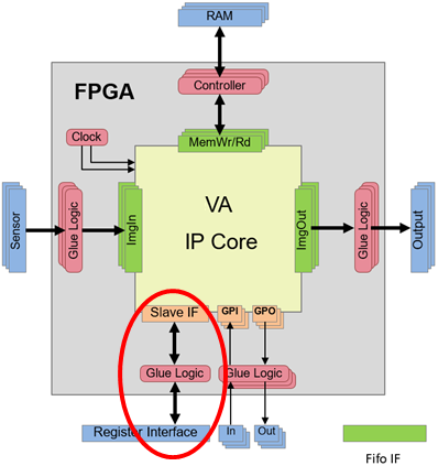
Dynamic design parameters (i.e., dynamic parameters of operator instances in an image application) are communicated via the register slave interface. The interface provides read and write operations.
The register interface has the following properties:
-
I/O is synchronous to clock iDesignClk.
-
Reset and Enable signals have no effect on register values.
-
The data width is 32 bit.
-
The address width of the interface is 16 bit.
-
Write and read may occur simultaneously.
-
Registers which are accessed through the register interface may have any width between 1 and 64. Mapping between the slave interface data width and the actual register width of a VisualApplets parameter is done automatically. When the width of a parameter register is bigger than the width of the register interface the runtime software will divide the access automatically. A single parameter then consumes more than one register address.
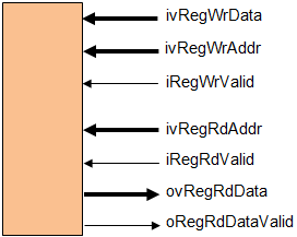
The figure above shows the ports related to the register interface.
Writing: The communication protocol for writing is based on the write address ivRegWrAddr, the write data ivRegWrData and the write strobe iRegWrValid. Any assertion of the high active signal iRegWrValid initiates a single write access to a VisualApplets register with the address ivRegWrAddr. Write accesses can be done in subsequent clock ticks so implicit bursts are allowed.
Reading: The communication protocol for reading is based on the read address ivRegRdAddr, the read strobe iRegRdValid, and the valid signal for read data oRegRdDataValid where the data is then output at the port ovRegRdData. Any assertion of the high active signal iRegRdValid initiates a single read access from a VisualApplets register with the address ivRegRdAddr. The latency of the returned output value may depend on the configuration of the eVA IP Core and the VisualApplets design.
When running a VisualApplets design in the VA IP Core on your hardware platform, the parameters are accessible via the VisualApplets runtime software interface.
VisualApplets supports different models for accessing design parameters at runtime:
-
Using an eVA runtime environment based on HAP files This approach is very similar to the runtime interface of frame grabbers from Basler. The HAP file contains all necessary information for accessing design specific parameters easily. A runtime software API is provided which can load HAP files, extract the FPGA configuration data, and provide access to the design parameters.
-
Using GenICam API based on generated GenICam XML code When the target platform is connected via a GenICam compatible interface to the software this option allows a seamless integration of image processing parameters into the GenICam API. There is no need for any additional software component.
-
Using generic, design- specific C API code generated by VisualApplets The generated code is platform independent ANSI-C code. Callback functions for write and read access to registers via the VA IP Core register slave are registered at startup. Then the code provides access to parameters addressed by name where translation functions trigger the communication via the call back functions. This approach is well suited for software integration in embedded systems (e.g., Zynq7000).
![[Note]](../common/images/admon/note.png) |
Automatic Generation of Runtime Interface Files |
|---|---|
|
The files for a design-specific runtime interface are automatically generated by VisualApplets (for all three access models). The options for the runtime software interface are described in detail in 'Runtime Software Interface'. |
The VA IP Core uses the register slave interface also for controlling the Reset and Enable signals – instead of using dedicated ports for that purpose. This way, Reset and Enable are under user control via the runtime software, and a not a priori known number of processes can be controlled separately.
The Reset and Enable signals interact with the VA IP Core design as follows:
-
Each process has its own Reset and Enable signals (high active) which are set by 1-bit registers.
-
Assertion of Reset puts the complete process in its init state.
-
Assertion of Enable starts processing.
-
Deactivating Enable stops processing. When Enable=0, input FIFOs are not read. Regarding output FIFOs, depending on the state of the image processing pipeline some data still may be written to them after deasserting Enable but the flow control safely prevents that any FIFO content gets corrupted.
-
Reset may only be asserted when Enable=0.
-
Reset will empty all FIFOs.
-
Enable has effect on any hardware specific operator with FIFO interface.
-
Reset and Enable have no effect on the parameters of the operators.
-
Reset and Enable have no effect on the GPIO ports.
-
For any ImgIn and ImgOut interface of the IP core, there are the output ports ResetO and EnableO. Those outputs are connected to the according Reset and Enable signals of the process where the interface is used. Any logic attached to the concerning interface is therefore able to perform an appropriate action during the reset and disable state.
-
After deasserting Enable, the design needs to be reset before it is enabled again. Setting Enable = 0 and subsequently Enable = 1 without asserting Reset may lead to unpredictable behavior for some VisualApplets designs.
Recommended START procedure for a process:
-
Send Reset.
-
Assert Enable.
Recommended STOP procedure of a process:
-
Deactivate Enable.
-
Send Reset.
Any read or write access to the FIFO of any platform specific operator is enabled by the Enable signal of the concerning process (with some design dependent latency caused by the flow control). Also the Reset signal of a process is connected to the reset port of any I/O FIFO associated with that process.
