| Brief Description | |
|---|---|
|
File: \examples\Processing\Color\Bayer\Laroche_original_maVCL.va |
 |
|
Default Platform: mE5-MA-VCL |
|
|
Short Description Bayer Demosaicing Algorithm According to Laroche |
|
According to Laroche et al. [Lar94] the red, green and blue pixel values from a Bayer pattern [Bay76] can be extrapolated using the following algorithm:
In a first step all green pixel values (luminance values) are extrapolated with horizontal and vertical chrominance gradients
( and
and  ). The gradients are defined using a
 kernel:
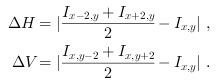
 is the
chrominance value (red or blue) on the pixel where the green value has to be interpolated.
Green
is the
chrominance value (red or blue) on the pixel where the green value has to be interpolated.
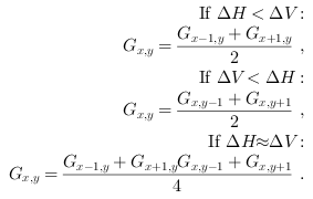
Green  is then
on the red and blue pixel positions:
is then
on the red and blue pixel positions:
From the interpolated luminance the missing red and blue pixel values can be calculated [Lar94]. Blue on a red pixel or red on a blue pixel:

blue on a green pixel in a red line or red on a green pixel in a blue line:
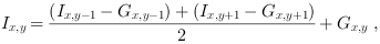
and blue on a green pixel in a blue line and red on a green pixel in a red line:
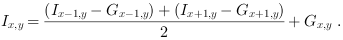
Here  is the color value red
or blue, that has to be determined.
The red, green and blue values on the red, green and blue pixels are the ones from the Bayer pattern input image.
is the color value red
or blue, that has to be determined.
The red, green and blue values on the red, green and blue pixels are the ones from the Bayer pattern input image.
The complete algorithm (\examples\Processing\Color\Bayer\Laroche_original_maVCL.va) is implemented in a VisualApplets design
for a microEnable5 frame grabber (marathon).
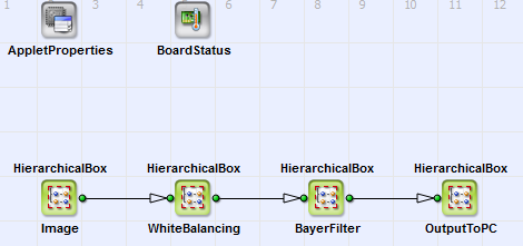
You can see its basic design structure in Figure 243, 'Basic design structure'. The content of the HierarchicalBoxes 图像 and OutputToPC is equivalent
to the basic acquisition designs, see e.g. 'Basic Acquisition Examples for Camera Link Cameras for marathon Frame Grabbers'. In the HierarchicalBox WhiteBalancing a white balancing equivalent to the example in
'Bayer 5x5 Demosacing with White Balancing' is performed.
In Figure 244, 'Interpolation step 1 of the Bayer demosaicing process' to Figure 246, 'Content of the HierarchicalBox BlueAndRed' the content of box BayerFilter
with detailed comments is shown: In Figure 244, 'Interpolation step 1 of the Bayer demosaicing process' the gradients  and
and  are calculated according
to Equation 8. The green values on red and blue pixels are determined according to Equation 9.
are calculated according
to Equation 8. The green values on red and blue pixels are determined according to Equation 9.
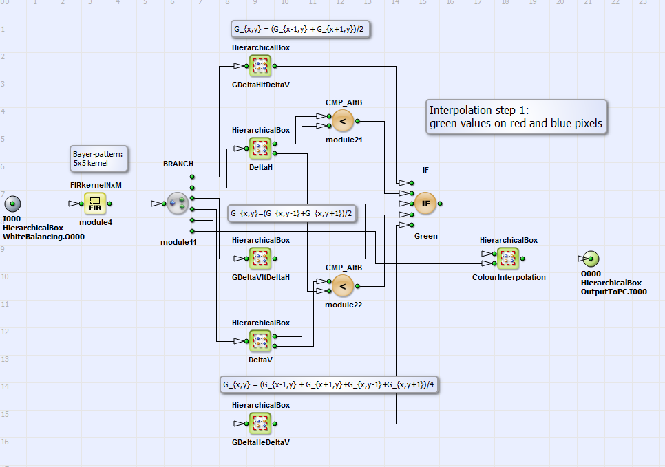
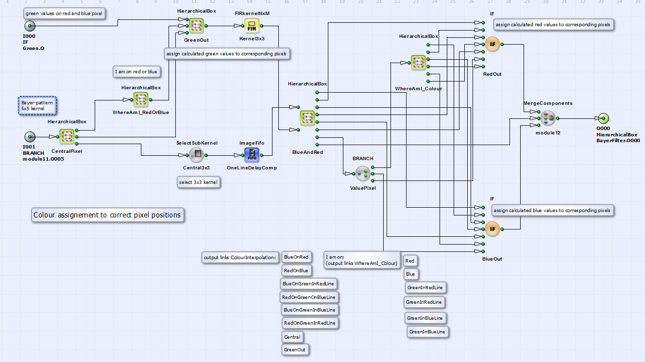
In Figure 245, 'Content of ColourInterpolation' the content of the HierarchicalBox ColourInterpolation is displayed: In the HierarchicalBox GreenOut
the green values of interpolation step 1 are determined as output green values if the current position is a red or blue
pixel. Otherwise, if the current position is a green pixel,
the output green value is the input green value from the Bayer pattern. The position determination takes place in WhereAmI RedOrBlue using
Modulo-,AND-, NOT and NotEqual-operators. In the HierarchicalBox BlueAndRed all red and blue values are interpolated
from the input Bayer pattern (using a  kernel) and the interpolated
green values according to Equation 9.
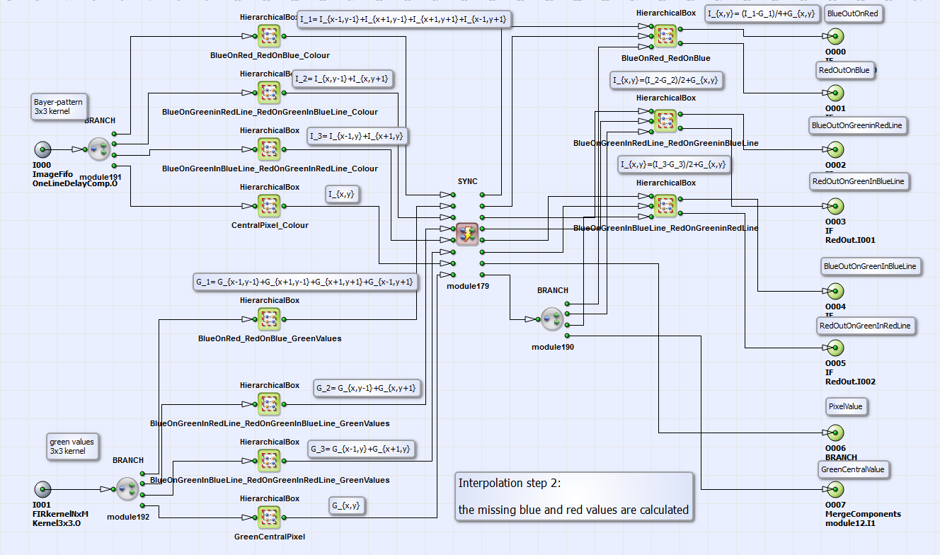
In Figure 246, 'Content of the HierarchicalBox BlueAndRed' you can see the content of the hierarchical box BlueAndRed with the interpolation step 2. The synchronization is performed not for a
kernel but for a sum of kernel values to save resources on the FPGA. Finally (see Figure 245, 'Content of ColourInterpolation') with the IF-operators RedOut and
BlueOut the calculated red and blue values are assigned to the corresponding pixel positions, which are determined in the HierarchicalBox
WhereAmIColour (analog to WhereAmI RedOrBlue).
kernel) and the interpolated
green values according to Equation 9.
In Figure 246, 'Content of the HierarchicalBox BlueAndRed' you can see the content of the hierarchical box BlueAndRed with the interpolation step 2. The synchronization is performed not for a
kernel but for a sum of kernel values to save resources on the FPGA. Finally (see Figure 245, 'Content of ColourInterpolation') with the IF-operators RedOut and
BlueOut the calculated red and blue values are assigned to the corresponding pixel positions, which are determined in the HierarchicalBox
WhereAmIColour (analog to WhereAmI RedOrBlue).
In Figure 248, 'Image demosaiced with the algorithm of Laroche et al. [Lar94]' you can see the result of the Bayer-demosaicing process with the implemented algorithm in comparison to the original artificial
color
image (Figure 247, 'Original color image') and an image demosaiced with an bilinear
 interpolation algorithm, using a VA-standard operator
Bayer5x5 (Figure 249, 'Image demosaiced with an bilinear
interpolation algorithm, using a VA-standard operator
Bayer5x5 (Figure 249, 'Image demosaiced with an bilinear  algorithm').


As a result you can see a reduced zipper effect and reduced false color artefacts in comparison to
the
 interpolation method.
